Bodywork for CFD
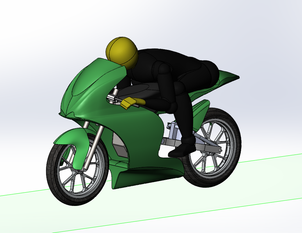
Motochanics 2019's edition Bodywork Geometry for CFD Simulation.
Motochanics is a project based in the University of Aveiro which consists on the development and construction of a racing motorcycle to participate in the MotoStudent competition.
Check out their Webpage: https://motochanics.web.ua.pt
Computer Fluid Dynamics simulations are extremely important in motorsport. It has become a substantial factor in the performance of a vehicle, especially at high speeds. It is crucial to know how the vehicle is interacting witht the airflow in order to generate the least drag possible while maintaining optimal levels of tire grip.
Prototype design plays the vital role for aerodynamic performance (check Motorcycle Bodywork for Motochanics-UA).
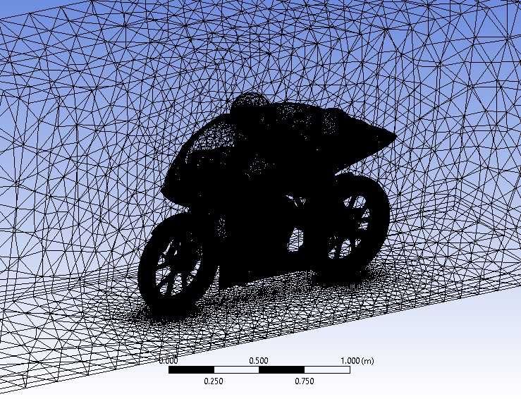
Simulating the airflow around a big assembly of components with complex designs can be very problematic. It was of extreme importance to simplify the geometry as much as possible without compromising the key geometric shape and dimension of the components. Finally, to maximize simulation efficiency and efficacy, higher mesh resolution was applied next to the prototype geometry and layers were added to the bottom of the "enclosure" volume.
Post-Processing is the step where the CFD results can be analysed and verified. There are a significant amount of tools that the user can use to retrieve useful data. Pressure contours and velocity streamline show the critical areas of the interaction between the airflow and the prototype's geometry.
In this section it is possible to see a compilation of pictures featuring essential steps to perform a CFD simulation of a Wind Tunnel for MotoStudent 2019 edition's motorcycle. Pictures range from design concepts, meshing and post-processing data.
Motochanics 2019's edition Bodywork Geometry for CFD Simulation.
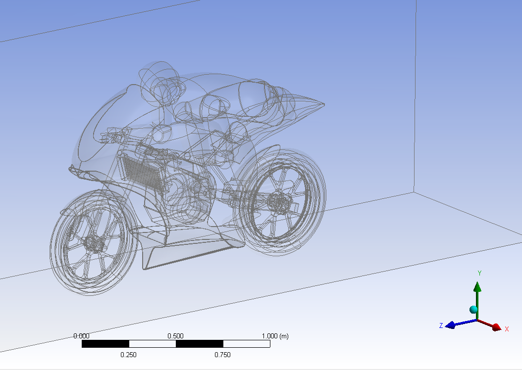
3D CAD geometry imported in Ansys Fluent and with the "enclosure" volume applied.
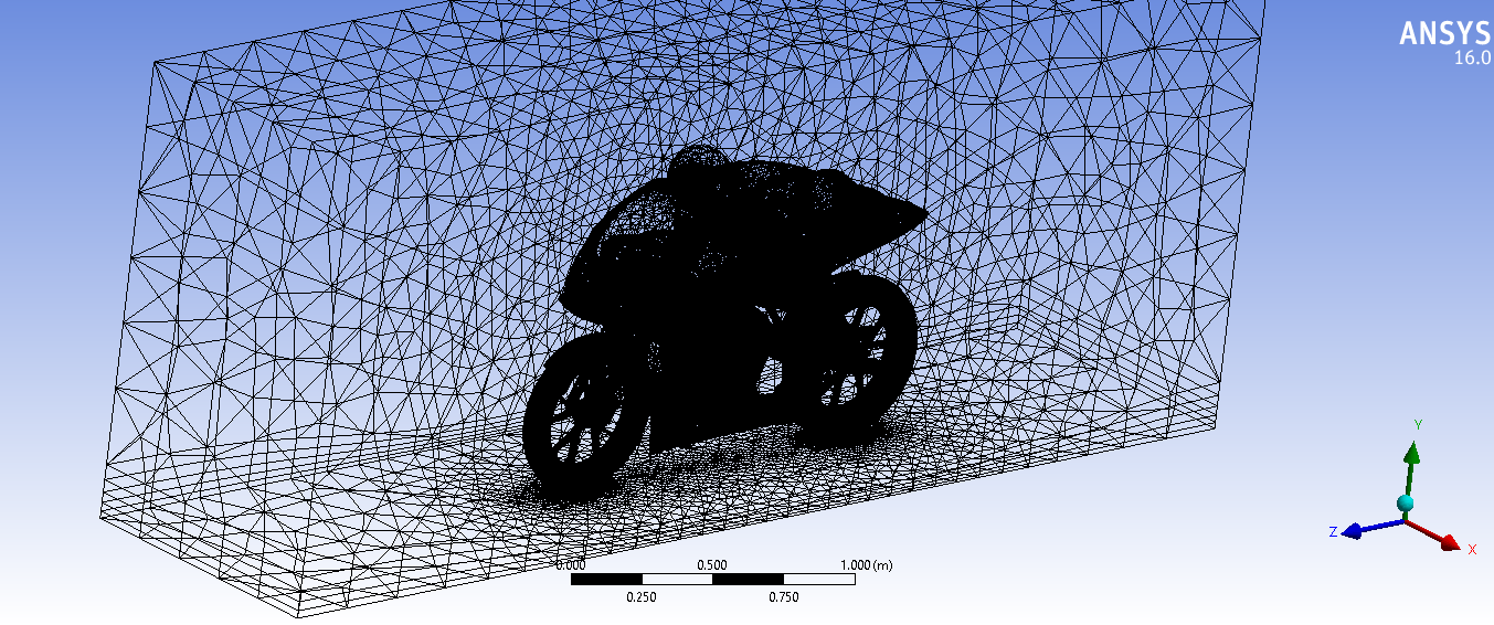
A good mesh is a vital part of the simulation. A careful meshing approach was taken to increase solving performance.
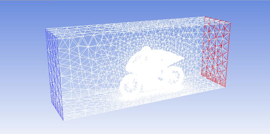
Defining Boundary Conditions for the CFD Simulation. Air will flow with a defined velocity from an inlet towards the outlet.
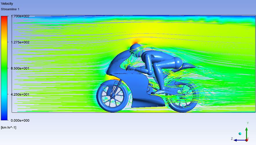
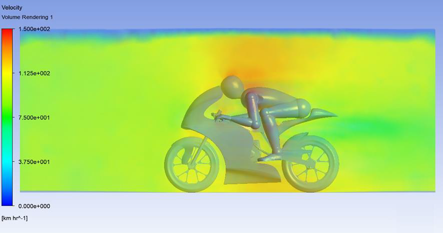
100 km/h Airflow through the geometry.
With the hidden geometry, it is possible to see air vortices forming inside the fairing and high pressure air flowing through the radiator.
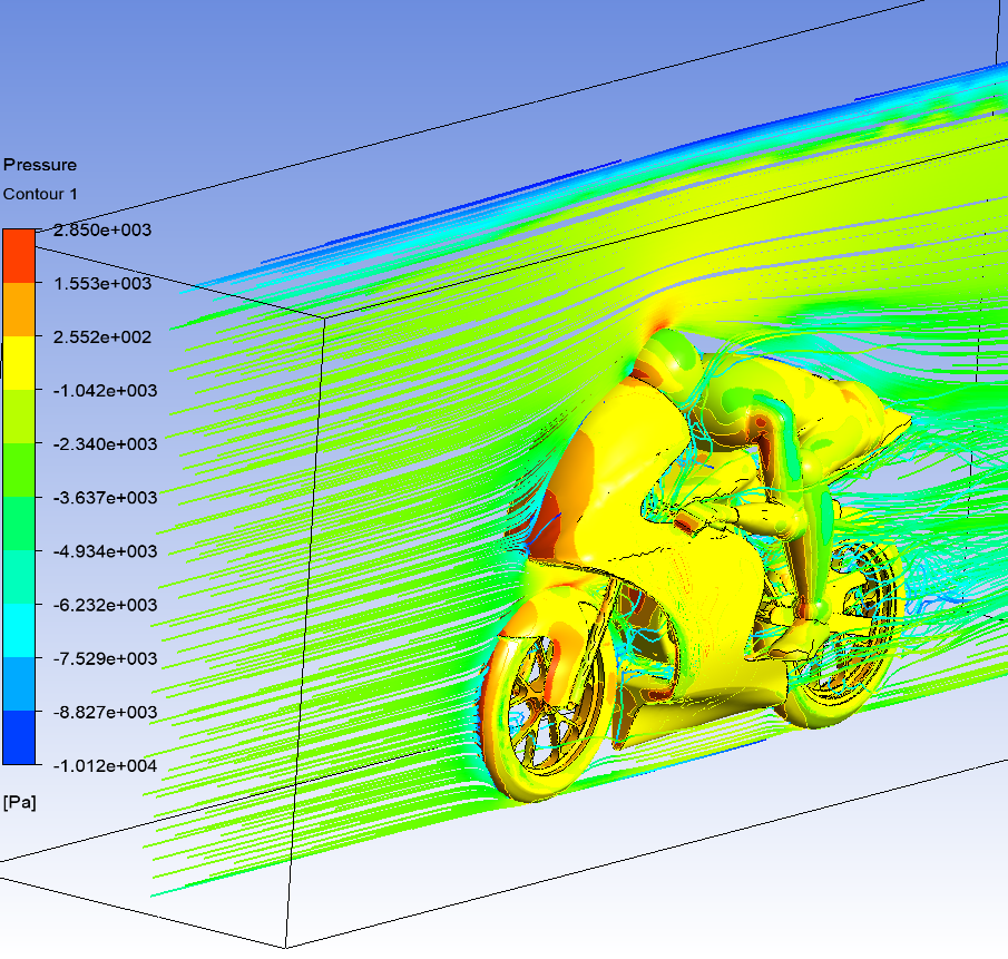
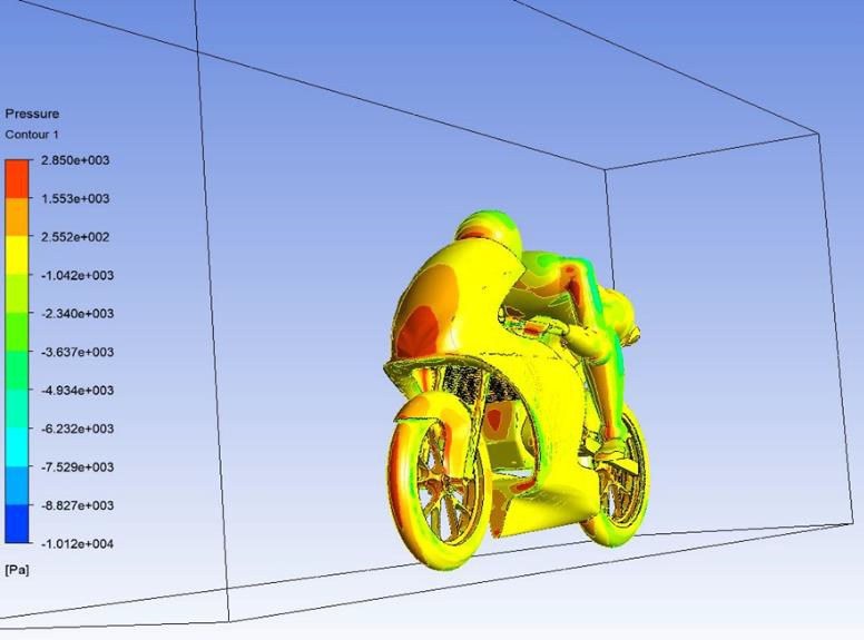
High and Low pressure air can be seen around the geometry with this visualization mode.
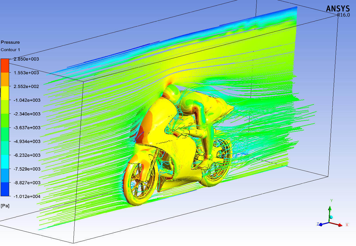
A middle plane containing the airflow velocity streamlines along with a pressure contour on the geometry.
Using the Pressure Contour visualization it is easy to see the higher pressure areas on the geometry.
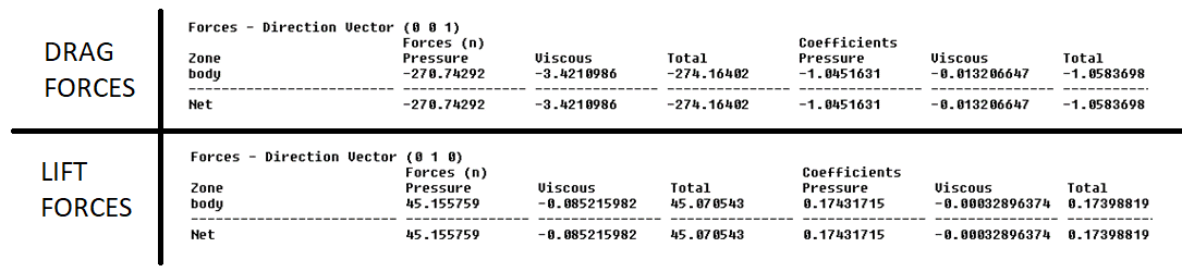
Drag and Lift are main aerodynamic forces to take into account when optimizing aerodynamic performance.
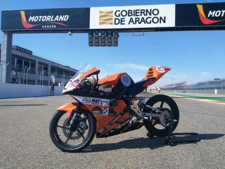
The prototype displayed at Motorland Aragón.
The first real challenge as a mechanical design engineer. To research and develop a complex competitive prototype that is limited to a tight budget and manufacturing operations. It was proof that a small team can build a performance prototype when synergy is at its best. Finally, it was an honor to become the first portuguese team to ever fully complete a Motostudent edition, not only being able to finish the entire race but also with a very good result!
CFD; Finite Element Analysis; CAE
3D CAD; CAE
Analysis of output data from ANSYS Fluent Post-Processing.