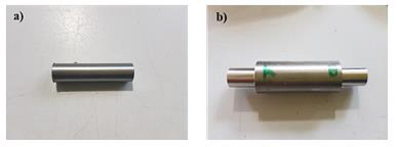
Specimen - Titanium Rod
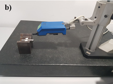
Open the picture to see the origanl specimen (a) and after being machined (b).
Using a lathe for the machining of a titanium rod and testing the results of using different machining parameters.
Group Project: 3 people
Performing cutting operations on materials of difficult machinability such as titanium. This material has a high grade of hardness, hence it offers an interesting case study. Maching operations (turning in this case), machining tool selection and cutting parameters are the crucial items to take into consideration.
Taking into practice the conducted study, the titanium rod would be machined on the university's CNC lathe and then geometrical and quality measurements would be taken in the mechanical engineering department's laboratory.
The titanium specimen was a 12 mm diameter cylinder with a length of 50 mm. The machining operations would be conducted using a CNC lathe with 18.7 kW of power and rotation speed of 4500 rpm. The main cutting parameters chosen for the reserch were: Cutting Speed (m/mm), Feed Rate (mm/rot), depth of cut (mm) and cutting fluid usage.
After each machining operation, the sample would be taken to the laboratory to analyse the geometrical tolerance of the part and also the surface finish. Samples of the machining chips would also be kept and analysed.
At the laboratory, the diameter of the cylinder would be measured using a micrometer. For the surface finish, a roughness tester would be used along the length of the specimen. Comparing the results obtained through metrology with theoretical expectations, it was seen that the best surface finish was obtained using the intermediate feed range instead of the smallest. It was also seen that using cutting fluid would not enhance the quality of the surface finish, resulting in slightly worse values for most of the experiments.
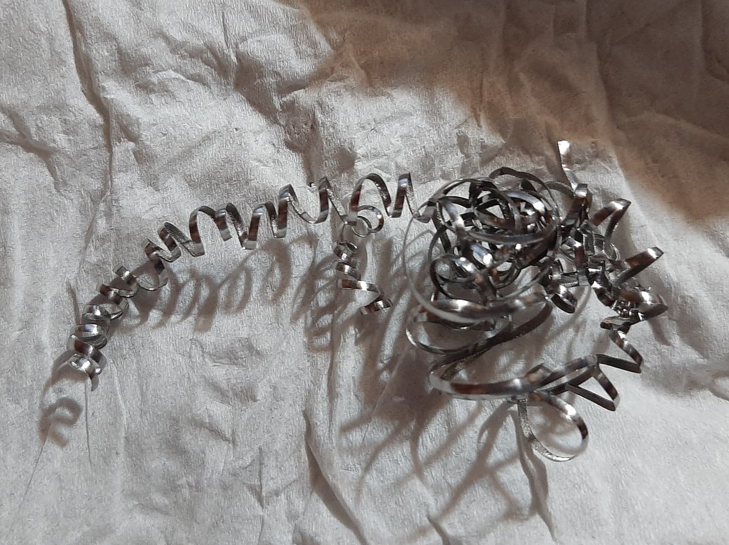
Finally, most of the chips were in the shape of a long edged helical, spiral and ribbon.
A compilation of pictures and diagrams featured for this project, containing the machining equipment setup, laboratory tools, specimen and resulting chips from the machining process.
Open the picture to see the origanl specimen (a) and after being machined (b).
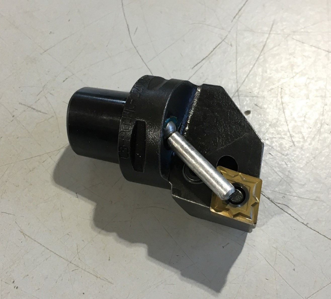
The chosen machining tool insert was CNMG 120408 MF1 TS2000 from SECO tools on a C3-PCLNL-22040-12 SANDVIK support. A bit of tool wear can be seen at the tip, resulting from machining the titanium rod.
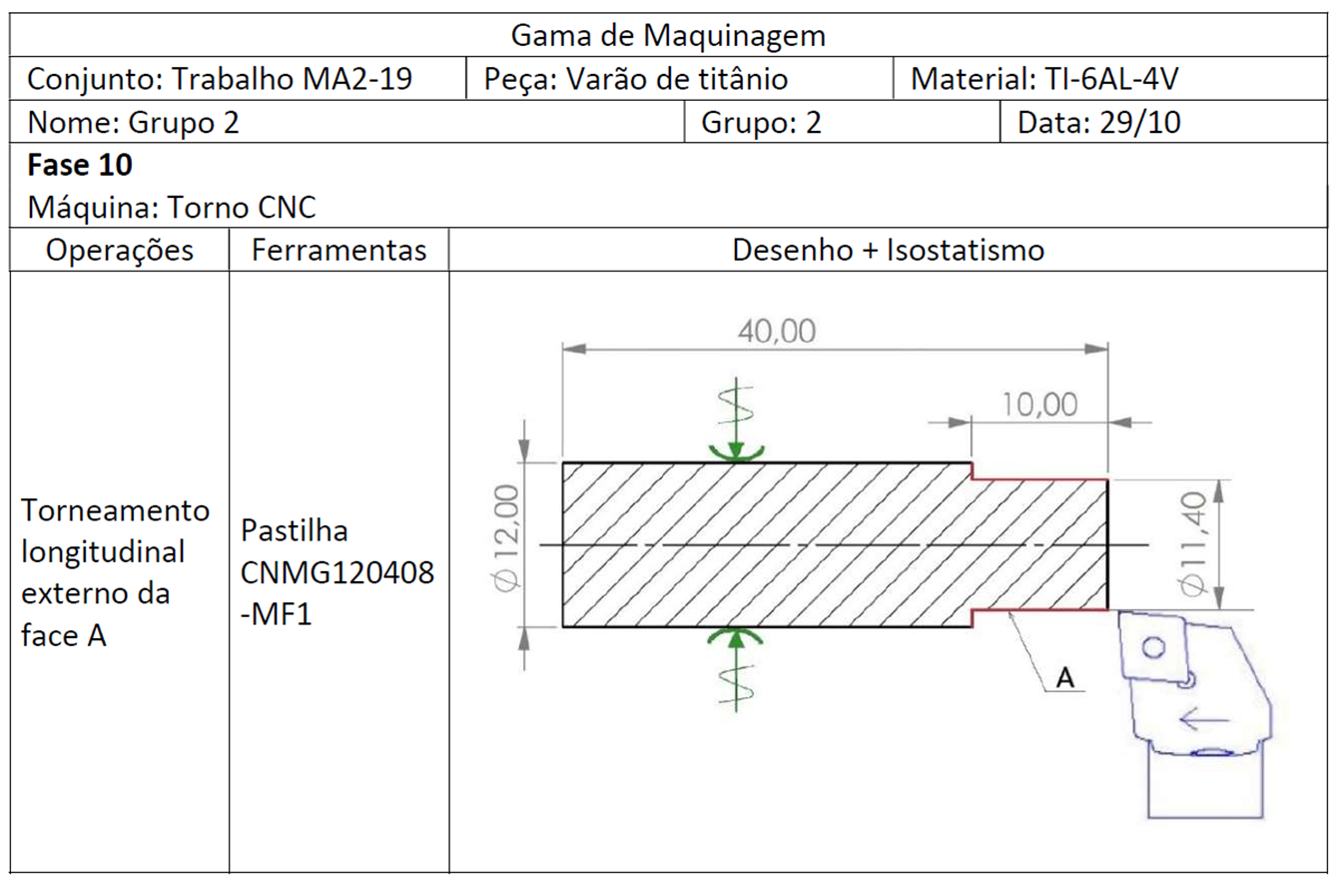
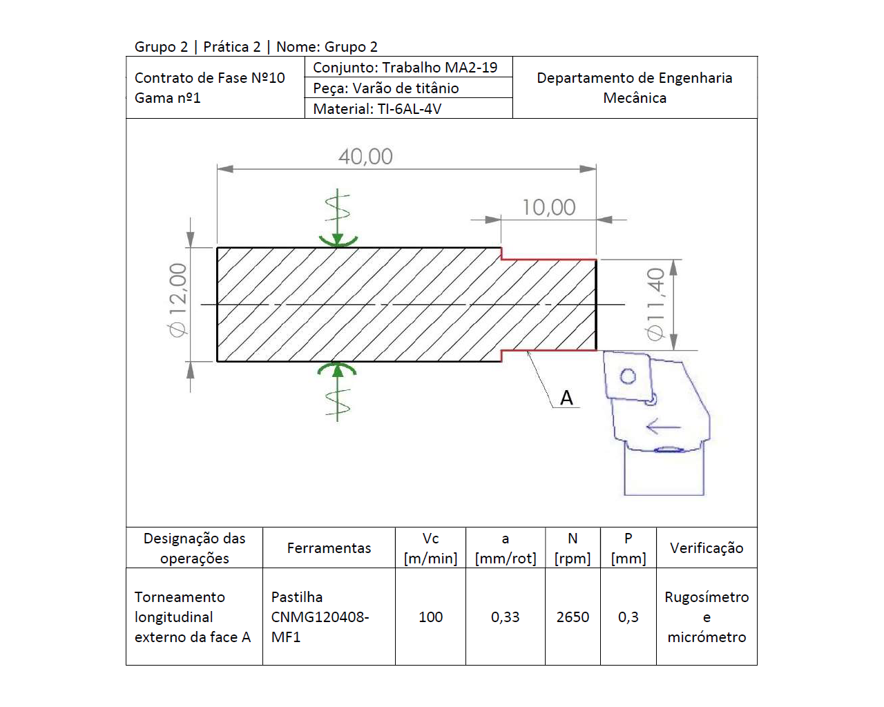
Diagram describing the machining operation setup: Turning operation and sketch.
This diagram contains crutial cutting parameters for the machining operation: Vc = cutting speed; a = feed rate; N = rotation speed; p = depth of cut.
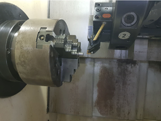
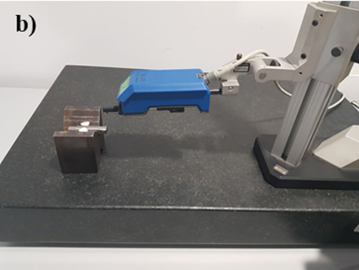
Equipment set in place to perform the machining operations.
A short video of the machining operation.
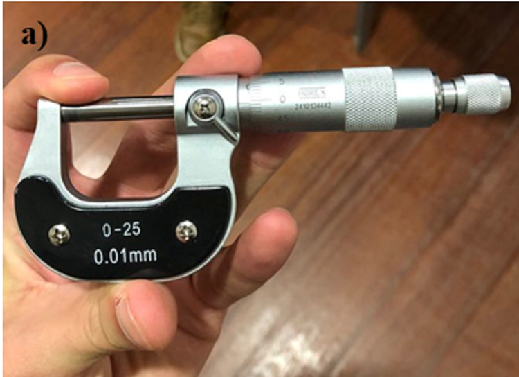
Device used for metrology purposes, it provides accurate measurements of components.
This device was used to obtain an accurate measurement of the surface roughness (μm - micrometers).
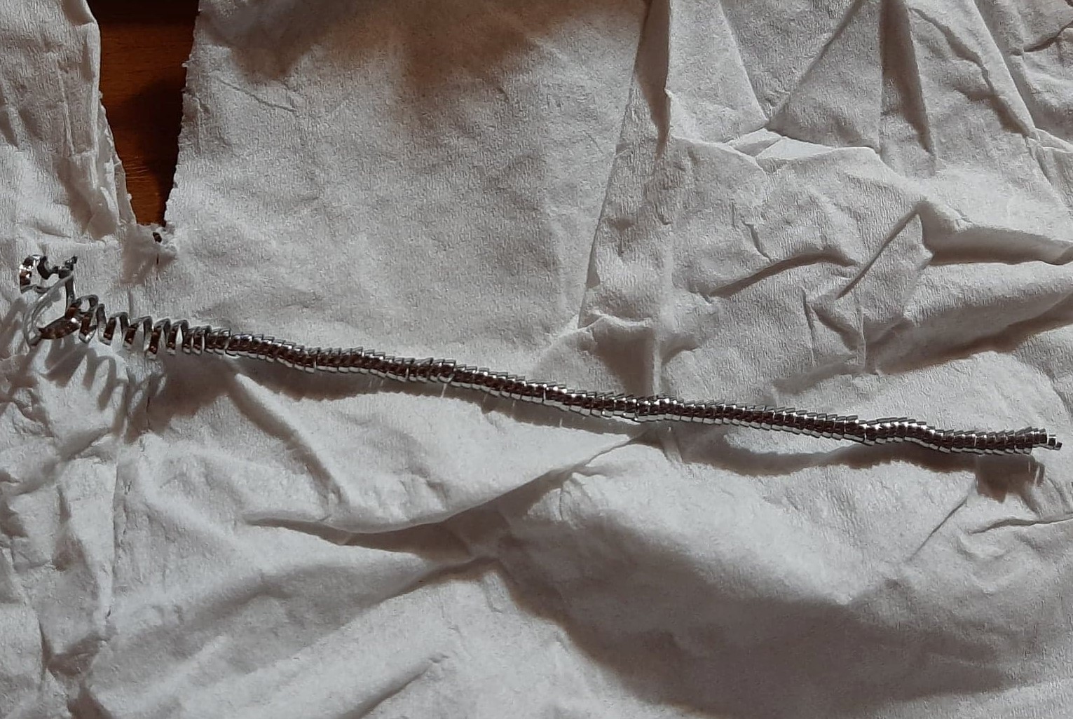
Long Spiral Chip
Long edged Helical Chip.
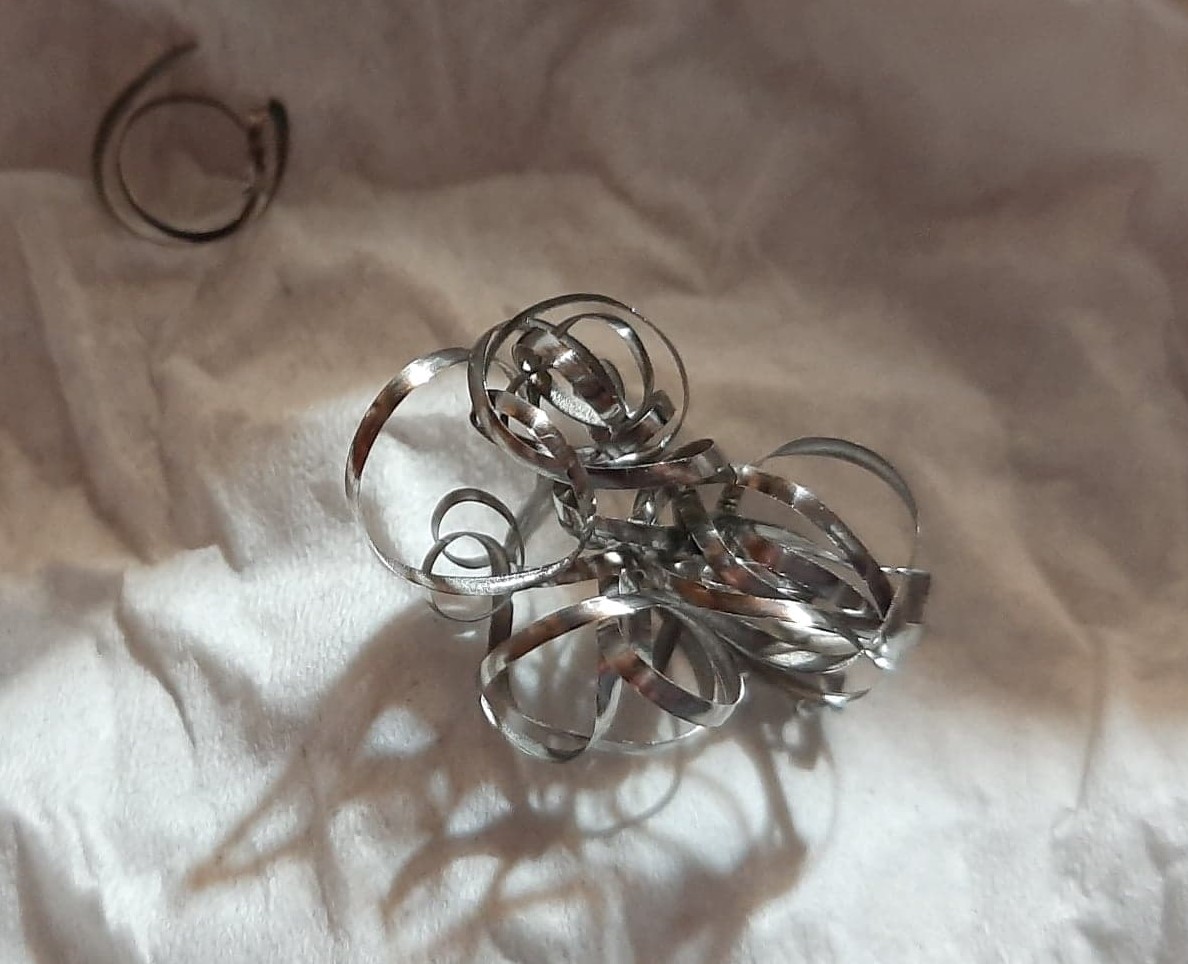
Snarled Ribbon Chip
Long Tubular Chip
In this project it was possible to carefully study and analyse a very important material used in so many different industries: Titanium. With the equipment available at the university, theoretical and experimental analysis were conducted and the results obtained were very interesting. Materials with hard machinability can present a challenge if precise and accurate dimensions are a requirement. Nevertheless, the project was a successful study opportunity.
Study of articles,conducting experiments and comparing results.
Calculate and compile data for analysis and comparison with article sources.
Find solutions to minimize material waste and diversify classes of experiments.