
Core Gears
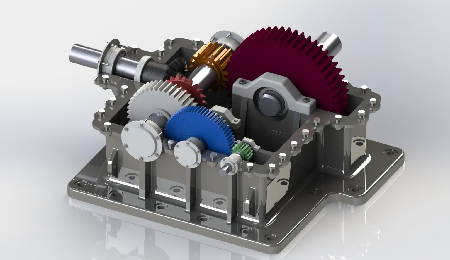
This is the first draft gear structure for the speed reducer.
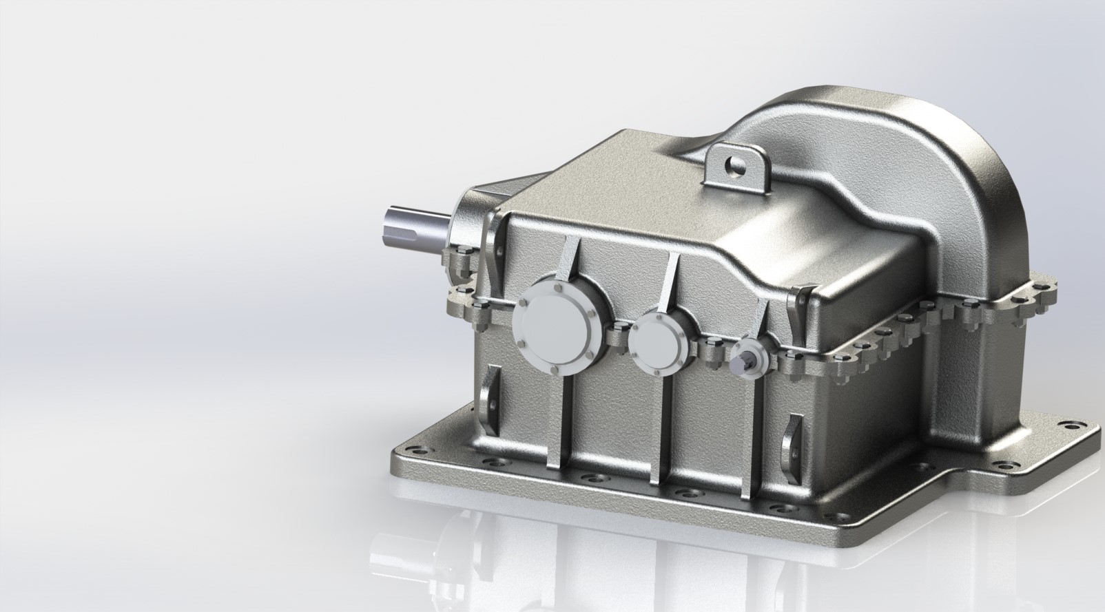
A speed reducer gearbox to be applied on an olive oil mill wastewater treatment station. The speed reducer provides two output shafts, one to drive a rotating arm and another for a transversal agitator assembled on it.
Group Project: 2 people
The mechanism needs to fulfill a certain set of requirements such as power and output speeds. To achieve such requirements, the project was divided in the following stages:

The device's casing was decided to be made in two halves. This would allow easy maintenance and also facilitate the casting procedure. The device would also incorporate appropriate sealing according to working environment conditions.

A compilation of pictures and drawings of the speed reducer gearbox.
This is the first draft gear structure for the speed reducer.

The first overview of what the final product would look like.

The final gear transmission structure. It is possible to visualize the shaft profile for assembly of elastic rings, bearings and gears.
High resolution layout: input shaft side view.

High resolution layout: rotating arm output shaft side view.


A technical drawing of the speed reducer.
This project involved a constant need of adaptation due to the many possible equipment failure situations. It was crucial to ensure that calculations had no mistakes and that the system provides a safety factor high enough to resist unpredicted stress. It proved to be a good oportunity to understand the different stages of a project development and also a chance to analyse what the market has to offer in terms of equipment, such as motors, bearings and gears.
3D CAD; CAE
Dimensioning and Selection of mechanical components.
Design for Manufacturing & Assembly