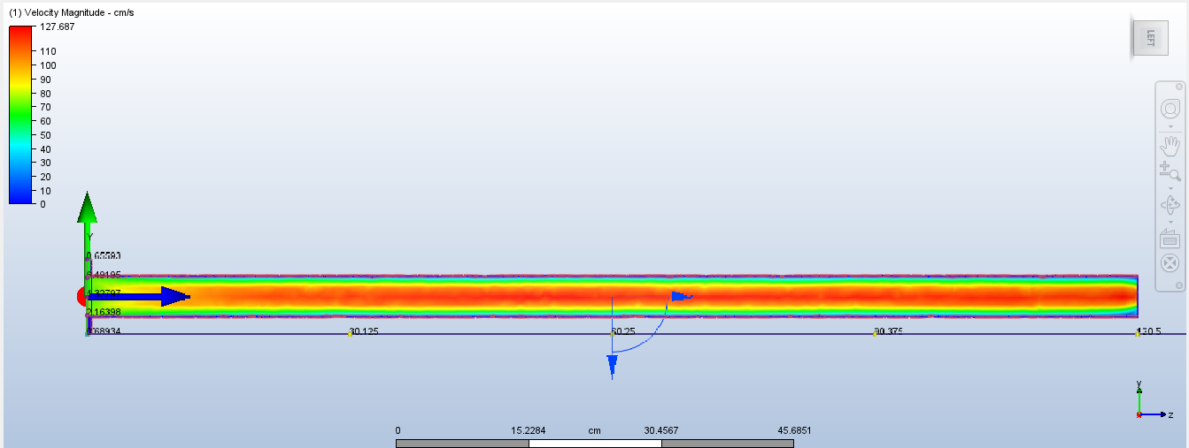
Benchmark - Straight Pipe
The design that provides a reference for designs to come.
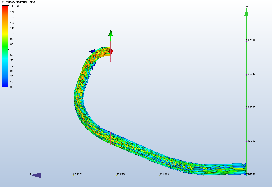
Pressure Drop = 0.86 Pa
Motochanics is a project based in the University of Aveiro which consists on the development and construction of a racing motorcycle to participate in the MotoStudent competition.
Check out their Webpage: https://motochanics.web.ua.pt
The main issue for an optimal exhaust geometry is the very limited space around the engine. Furthermore, engine exhaust gases are expelled at very high temperatures, causing the exhaust itself to considerably heat up and possibly damage nearby components or the rider.
The exhaust system must comply with competition's noise regulations. With all these factors together, geometry and path optimisation are essential to maximise engine performance.
The main objective was to minimise pressure drop throught the length of the exhaust. The first design was a straight pipe with an estimated needed exhaust length. This design would set up the minimum possible pressure drop for this system and thus it became the benchmark for the designs to come. The challenge was then design a geometry that would fit in the space available in the motorcycle and try to minimise pressure drop through small geometry and cross section diameter changes.
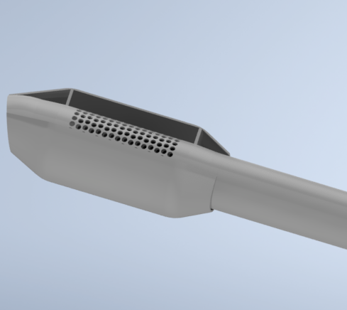
The muffler design is very important because there are noise regulations in the competition. The preferred scenario was having a muffler installed in the exhaust without compromising too much pressure drop. Following some research articles, a perforated muffler such as demonstrated in the picture would provide the wanted performance while complying with competition regulations and be easy to manufacture.
In this section it is shown a compilation of pictures featuring exhaust desing and also the step by step methodology to achieve the best performing exhaust geometry. It is also shown the picture of the 2021's Motochanics motorcycle.
The design that provides a reference for designs to come.
Pressure Drop = 0.86 Pa
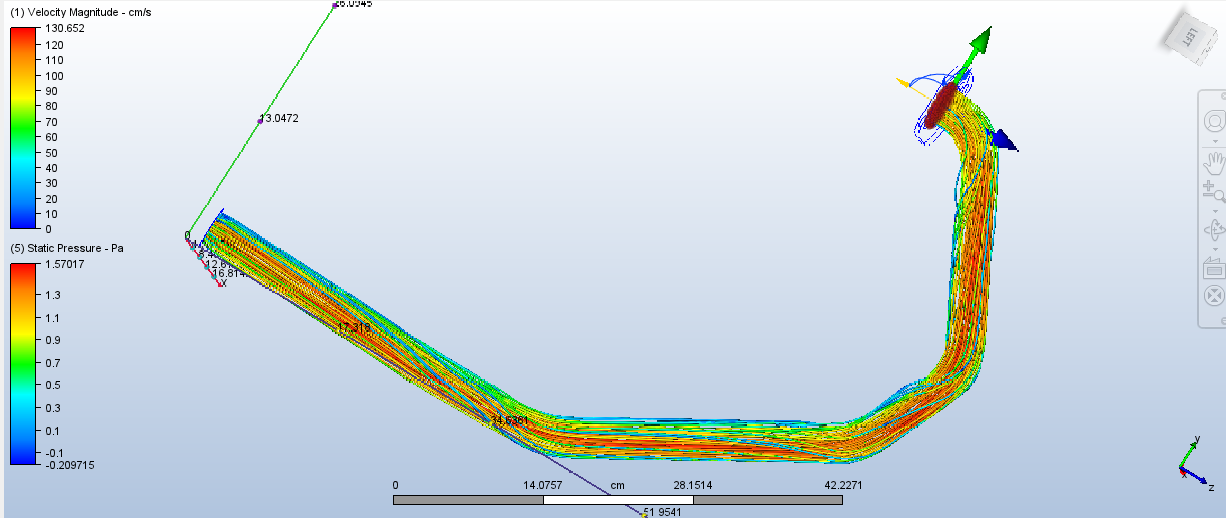
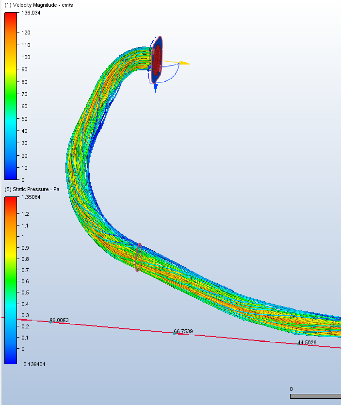
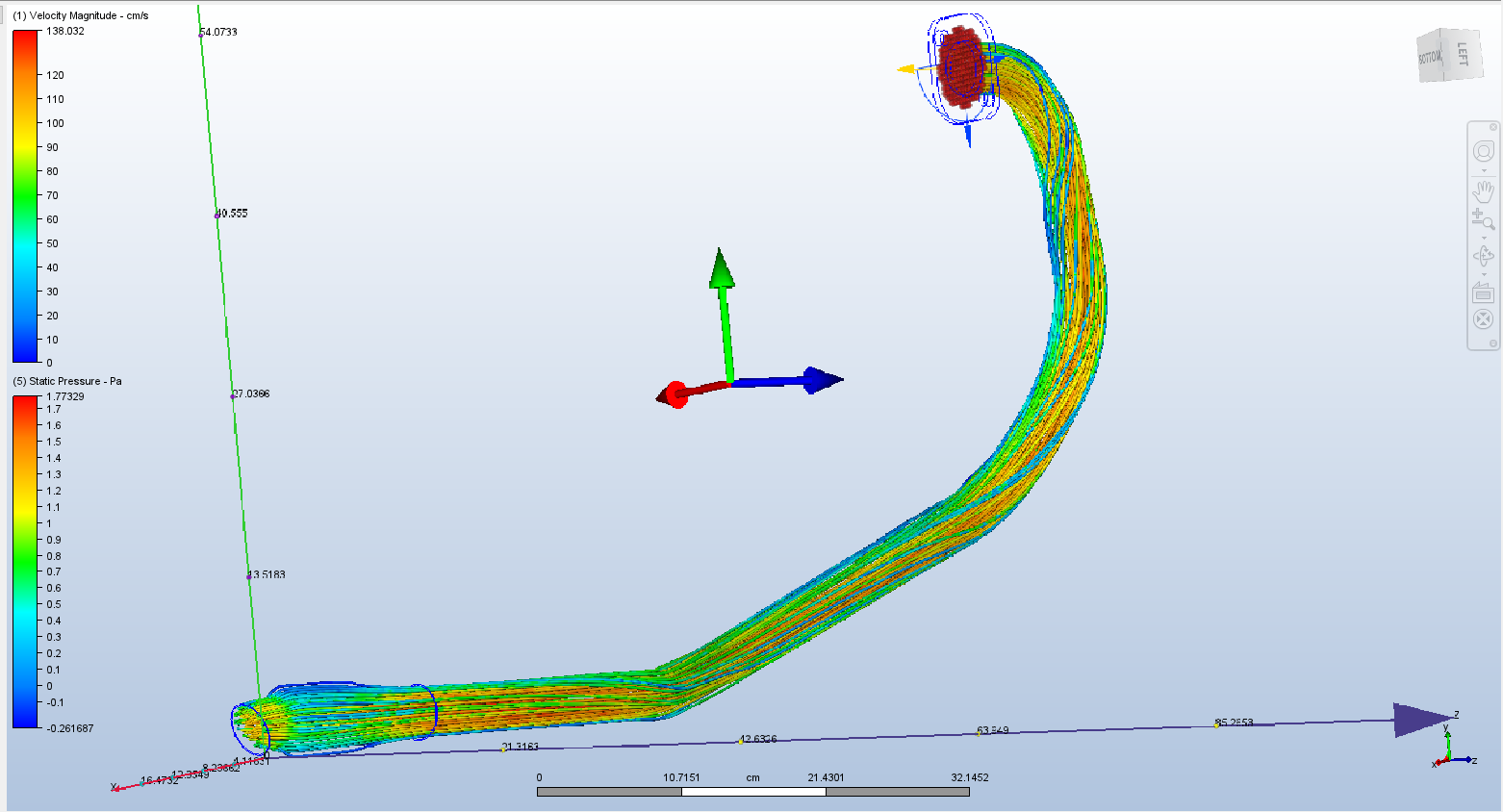
Using the space available between components, this would be the optimal path for the exhaust system.
Pressure Drop = 1.37 Pa (increase of 0.51 Pa)
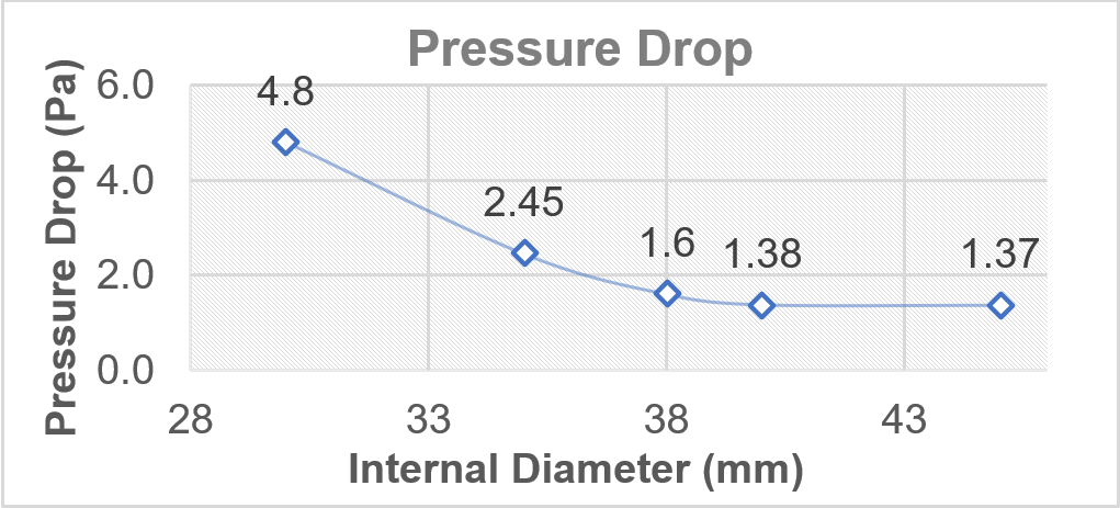
The optimal diameter was 45 mm, however it would result in considerable extra weight, hence the 40 mm diameter design was chosen.
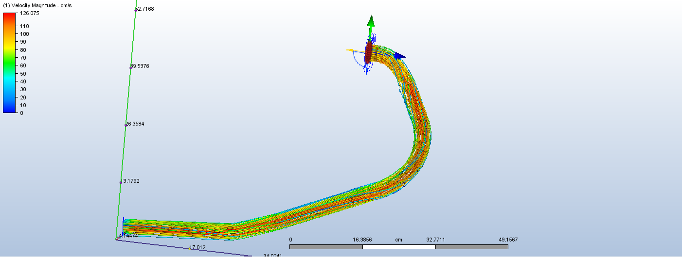
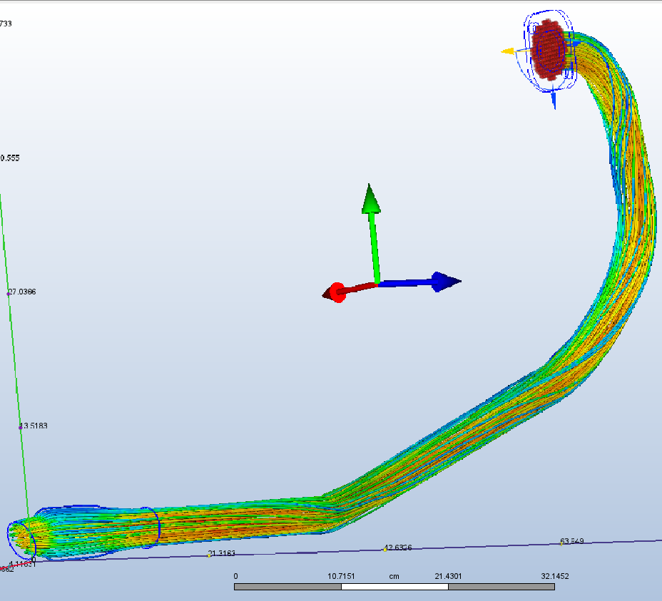
Analysing CFD results, it was seen that smoothing some of the geometry's curves it was possible to decrease the pressue drop, resulting in a new and enhanced exhaust version.
Pressure Drop = 1.27 Pa (decrease of 0.11 Pa)
A new design where the cross section diameter would progressively increase was tested and results were promissing.
Pressure Drop = 1.075 Pa (decrease of 0.195 Pa)
Previous design was too complext to be produced hence it was decide to have two cross section diameter changes over the exhaust's length.
Pressure Drop = 1.11 Pa (increase of 0.035 Pa).
Total Pressure Drop Decrease = 0.27 Pa (20%)
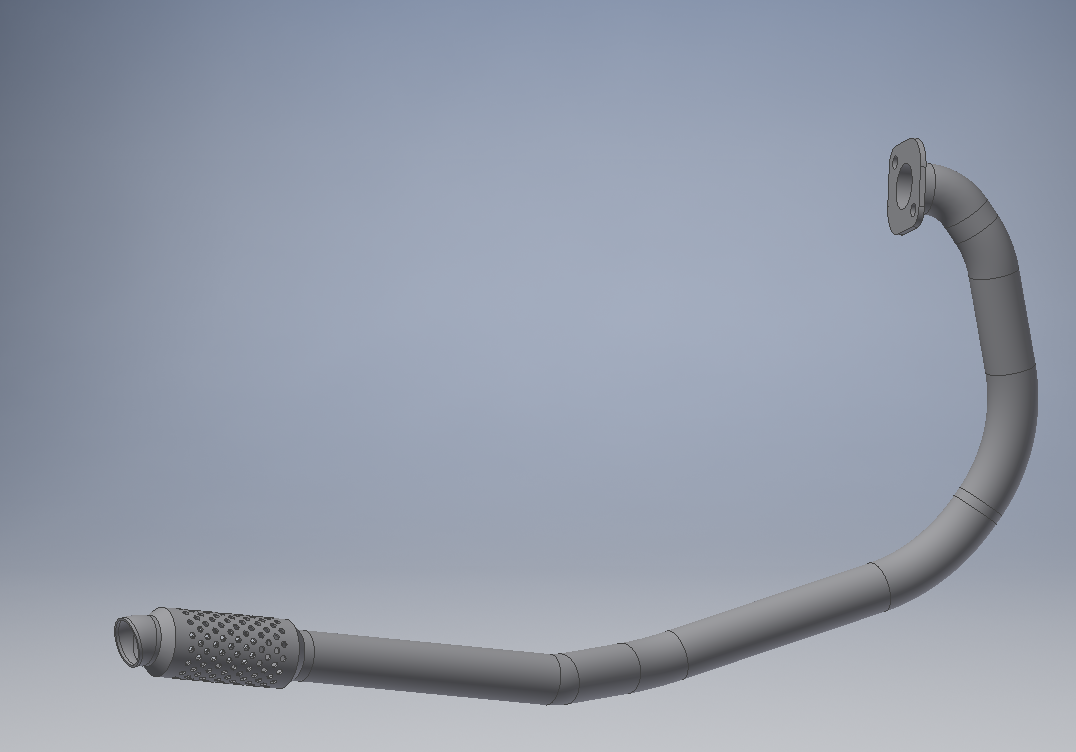
The complete exhaust whithout the muffler shell.
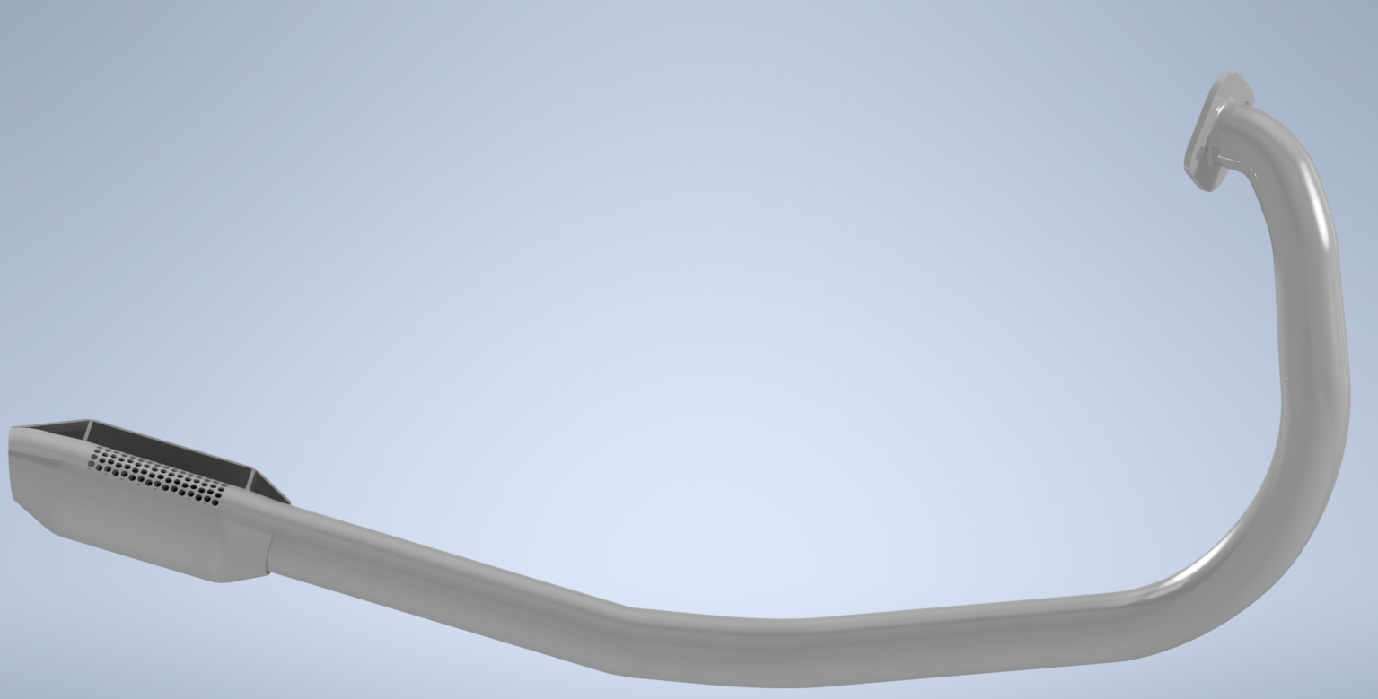
Exhaust representation with a virtual cut on the muffler shell for detailed view.
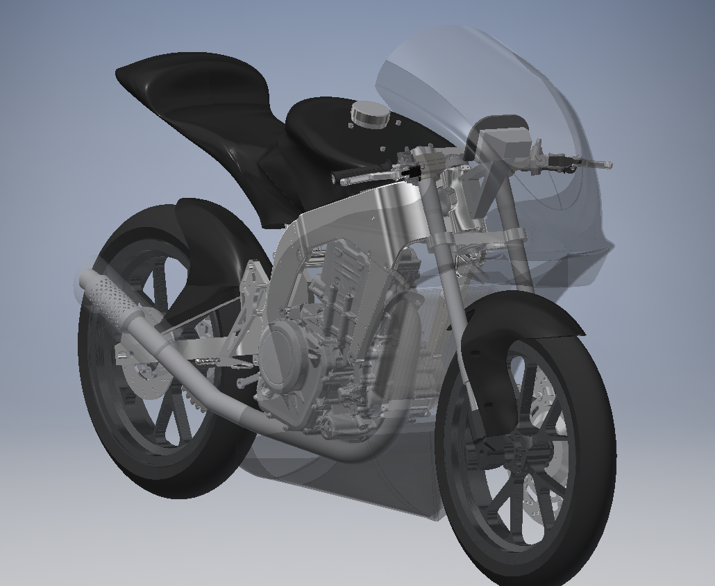
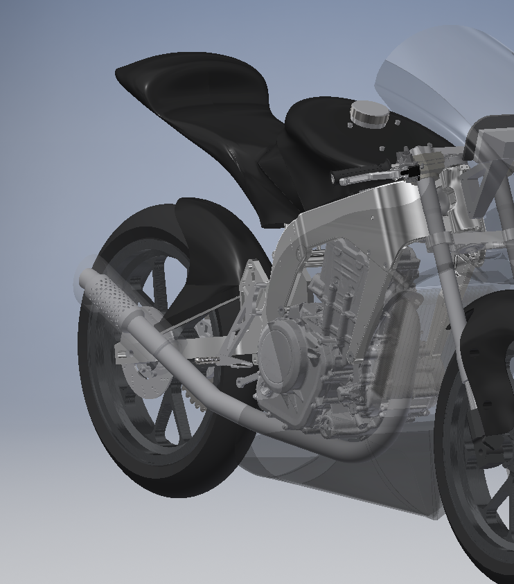
A perspective view of the concept's placement on the motorcycle.
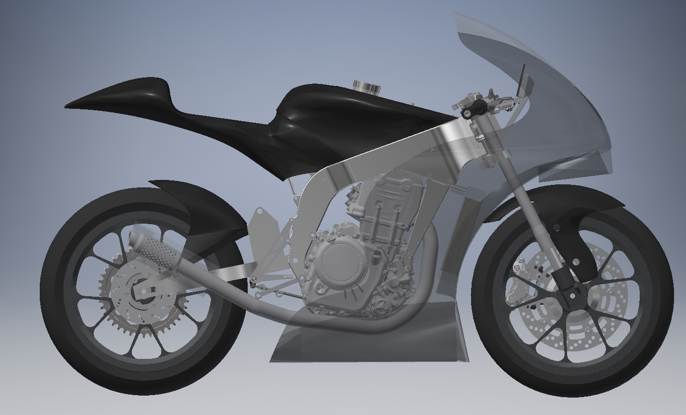
A side view of the concept's placement on the motorcycle.
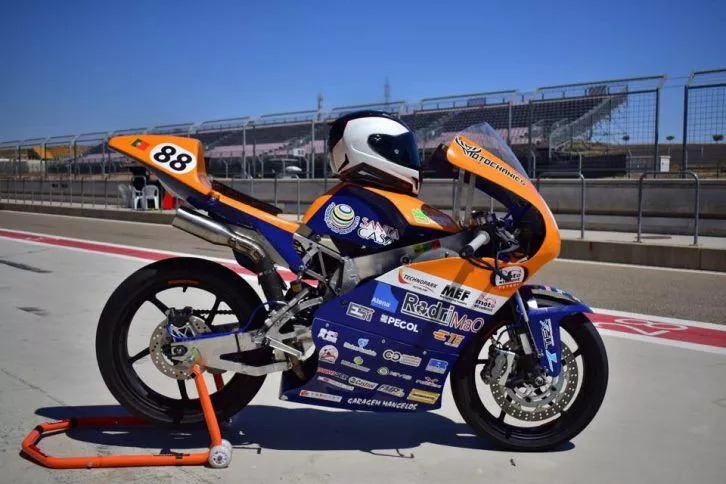
The prototype displayed at Motorland Aragón.
Previous Motostudent edition's experience provided a very solid background for a whole new project. The exhaust system design approach was very methodical so that step by step, issues within the design could be observed and corrected while also providing important feedback to improve on the overall design. Exhaust performance and weight were significantly improved. Overall, the team's objectives were reached as it was possible to improve the project's team score from a 23rd to 14th place (global project score) and a brilliant 9th place in the race (from 14th in previous edition).
CFD; Finite Element Analysis; CAE
3D CAD; CAE
Analysis of output data from Autodesk CFD.