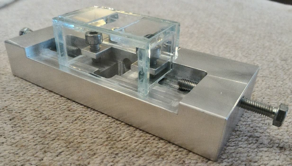
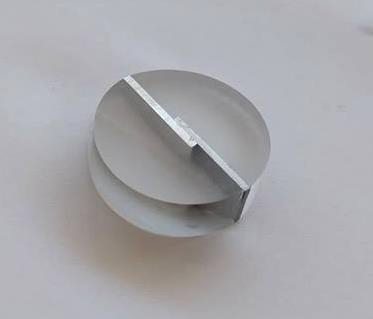
Fixing device
A device used to lock the specimens in place. It was designed and manufactured in the university.
A study of the welding possibility of two dissimilar metals: Dual-phase 1000 steel with aluminium, using a pulsed laser Nd:YAG.
Group Project: 3 people
The project consisted on the evaluation of the welding of DP1000 Steel specimens with aluminium ones, using a laser welding machine SISMA SWA300. The specimens were welding over each other, testing the following parameters:
The specimens's dimensions were rectangular 40x14x1.5 mm. Since steel has a higher melting point it was placed on top of the aluminium, resulting in material penetration during welding. Welding strength would be analysed using a tensile test machine. It was found that a specific combinatin of parameters would result in a strong welding strength, where after being tensile tested, the welded specimen breaks by the aluminium section.
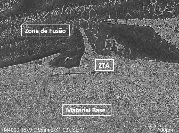
After finding the best parameters for a successful welding, the welded sample was treated and prepared for a microstructural analysis. Using an optical microscope it was possible to observe three zones: the fusion zone, the thermally affected zone and the interface between the two zones. With a SEM (Scanning Electron Microscope), a more detailed image of the interface between zones could be observed, where the differences in granular distribution between zones was easily identified.
In this section, a compilation of pictures taken for the projects report is shown featuring: fixing device for specimens (developed specifically for this project), welded samples and pictures from the microscopes.
A device used to lock the specimens in place. It was designed and manufactured in the university.
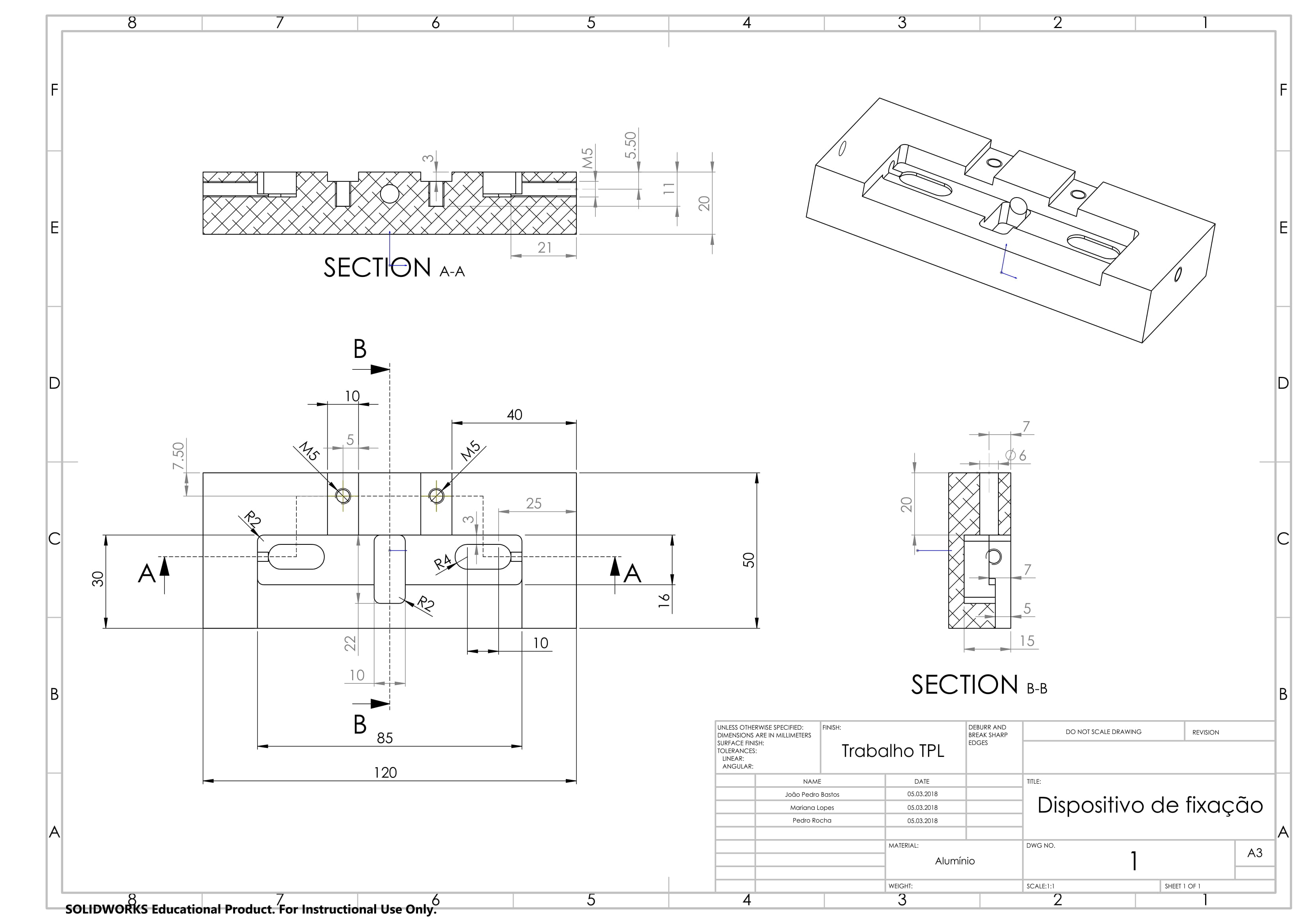
Technical Drawing of the device to be manufactured in the unversity's mechanical engineering department.
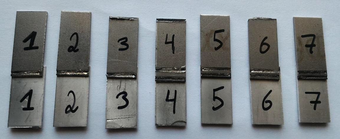
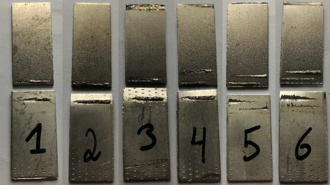
A set of seven samples of welded specimens.
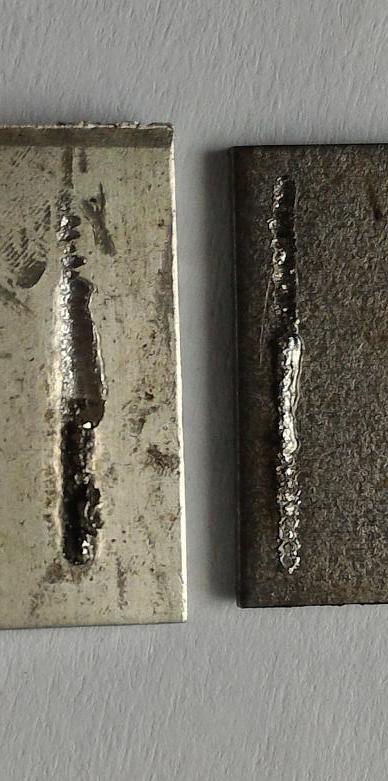
It is possible to see that the affected area of the laser progressively widens and deepens. This is due to the progressive increase in material temperature, resulting in an increased molten area.
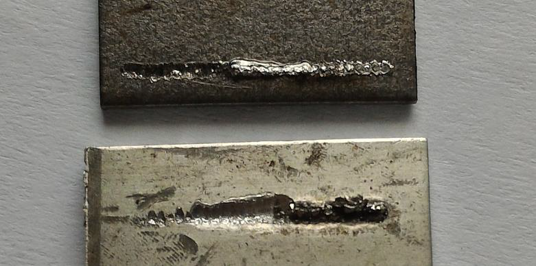
These samples broke from the welding area.
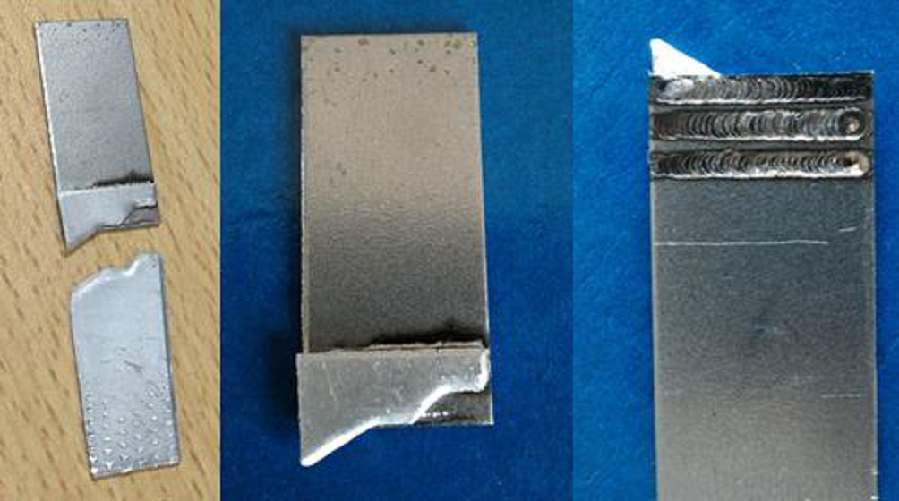
This sample's welding had a higher yield strength than aluminium's, hence the sample broke from the latter.
Prepared and cleaned in epoxy resin to be analysed on the microscopes.
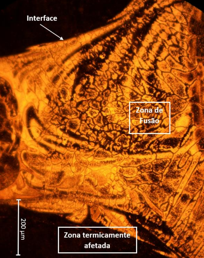
In this picture it is possible to see the fusion zone, the thermally affected zone and the interface between zones.
Using this microscope, a more detailed visualization of the thermally affected area is seen. Notice the granular composition around this area.
For this project it was given the opportunity to use very advanced equipment such as pulsed laser Nd:YAG technology, a high resolution optical microscope and a Scanning Electron Microscope. It was possible to achieve the desired results, as it was possible to weld two dissimilar metals while guaranteeing a strength superior to the weakeast material involved. Finally, the microstructural analysis provided a visualization of the fusion phenomenon between the two layers of materials.
Conducting experiments, comparing results and using laboratory equipment.
Find solutions to minimize material waste and diversify classes of experiments.