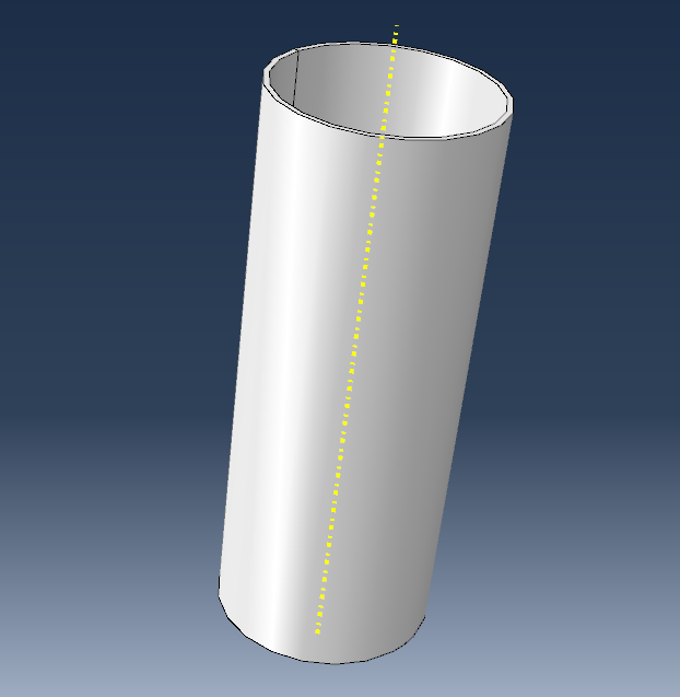
Raw Material
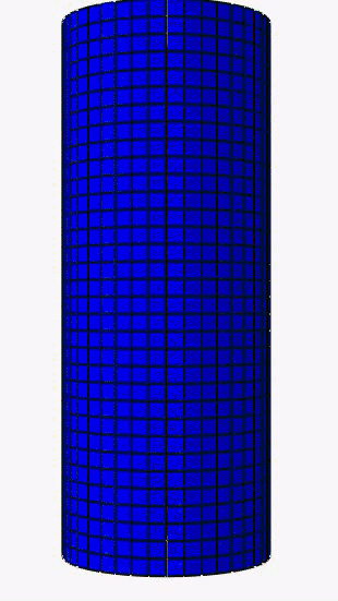
A C1010 Steel cylinder with 1.65 mm of thickness.
This project simulates in ABAQUS/CAE a technological process: Hydroforming an axisymmetrical metal piece.
It is a process that can be used to produce parts with complex geometries with no contact with tools, providing a good surface finish. Using water pressure, a 1.65 mm thickness tube will expand until its surface is pressed against a mould, which results in the required final geometry.
To successfuly simulate this technological process, it is crucial to increase the hydrostatic pressure step by step. For this project the material assigned to the geometry was C1010 Steel. To achieve desired product, pressure needed to be ramped up to 74 MPa. Six steps were used to slowly stabilize the increase in pressure, with the biggest increase being the latter.
A compilation of rellevant media for this project including essential geomety, animations and an overview of the steps and results.
A C1010 Steel cylinder with 1.65 mm of thickness.
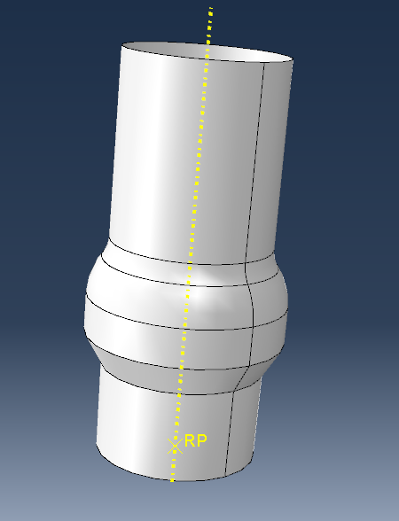
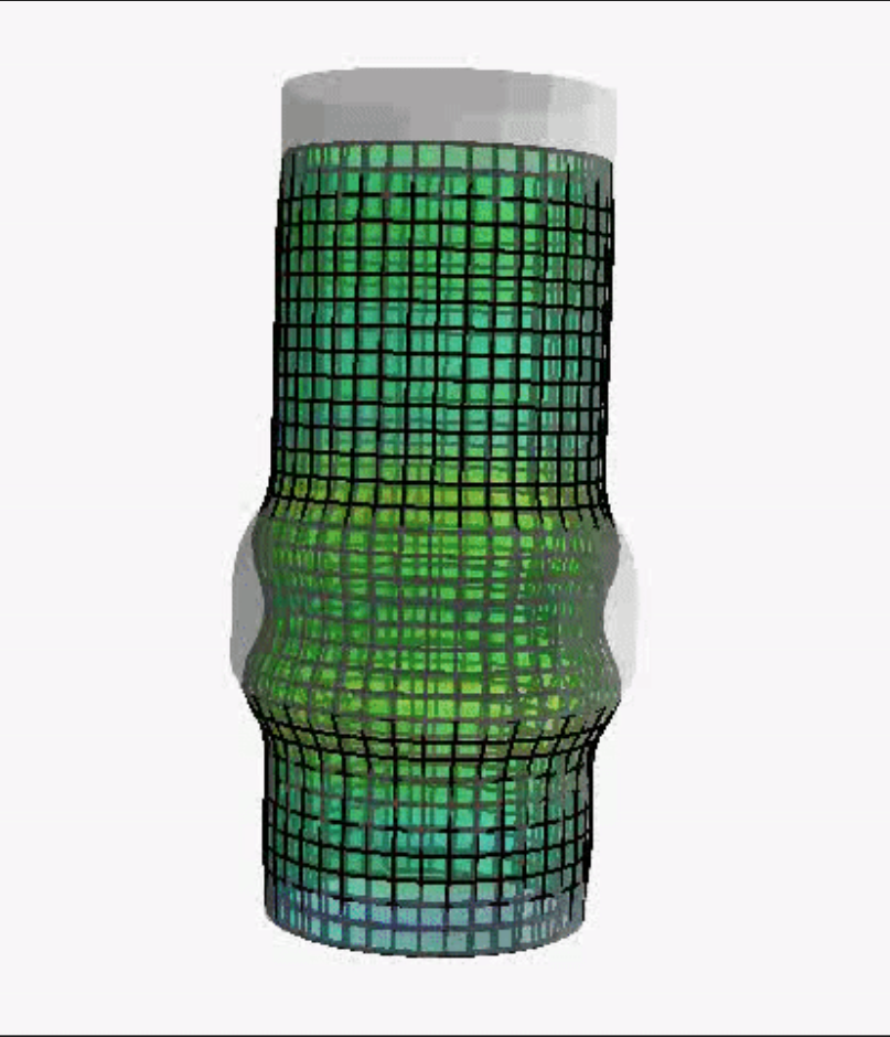
To replicate the process in ABAQUS/CAE, the mold tool surface is the key geometric element to procede with the simulation.
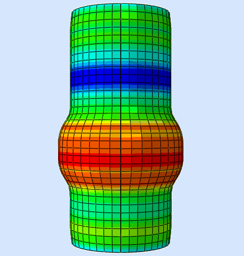
An animation demonstrating the raw material slowly being pressed against the molding tool.
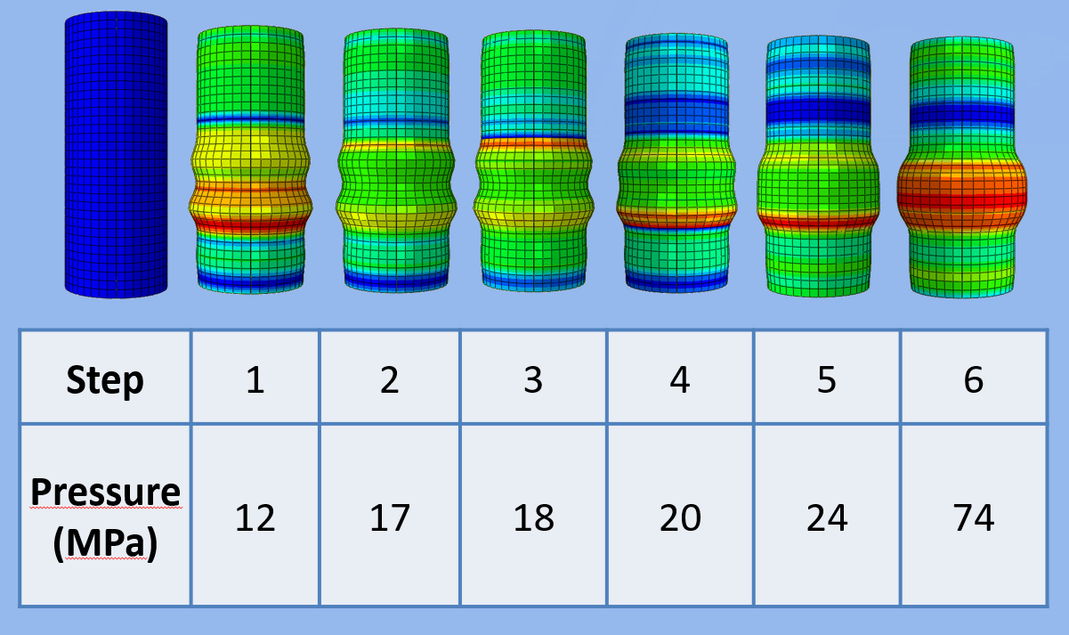
The six stages of the Hydroforming Simulation and their respective hydrostatic pressures.
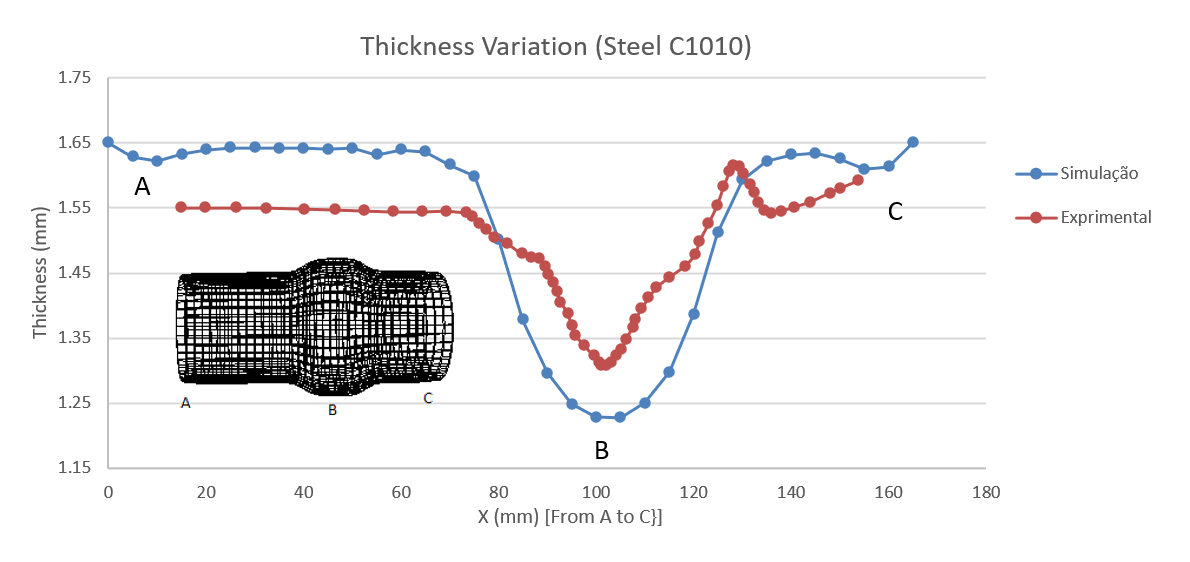
The red line represents the thickness across the geometry length taken from a real experiment, while the blue line represents the equivalent retrieved from ABAQUS/CAE.
Finite Element Analysis; CAE
Process ABAQUS/CAE output data and create plots, charts and data reports.