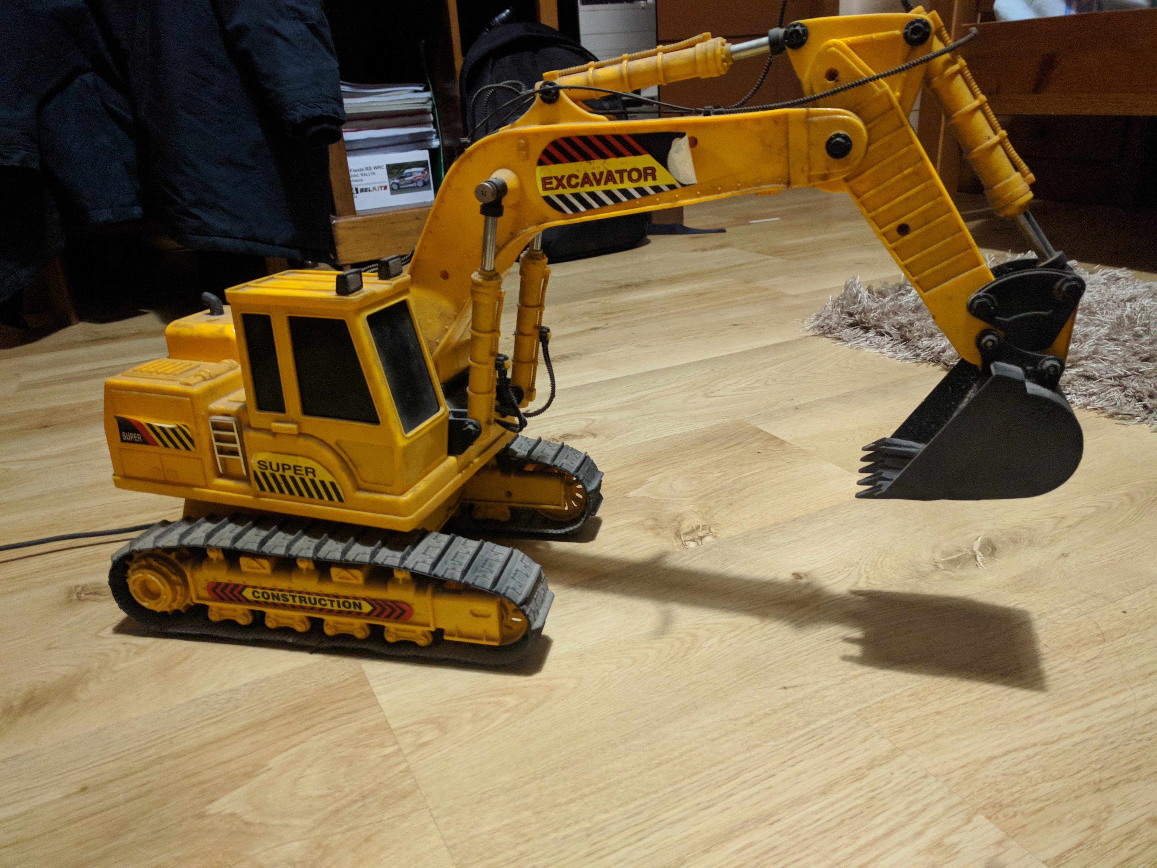
Excavator Replica
Fully assembled object
This project consists on choosing a real life object to be disassembled and then computer modelled using Solidworks as 3D CAD software.
Group Project: 4 people
The chosen object for the project was a replica of an excavator due to the amount of moving complex components that compose this object. This object provided an oportunity to incorporate gear transmission concepts for the moving hydraulic arm and for the wheel-tracks assembly.
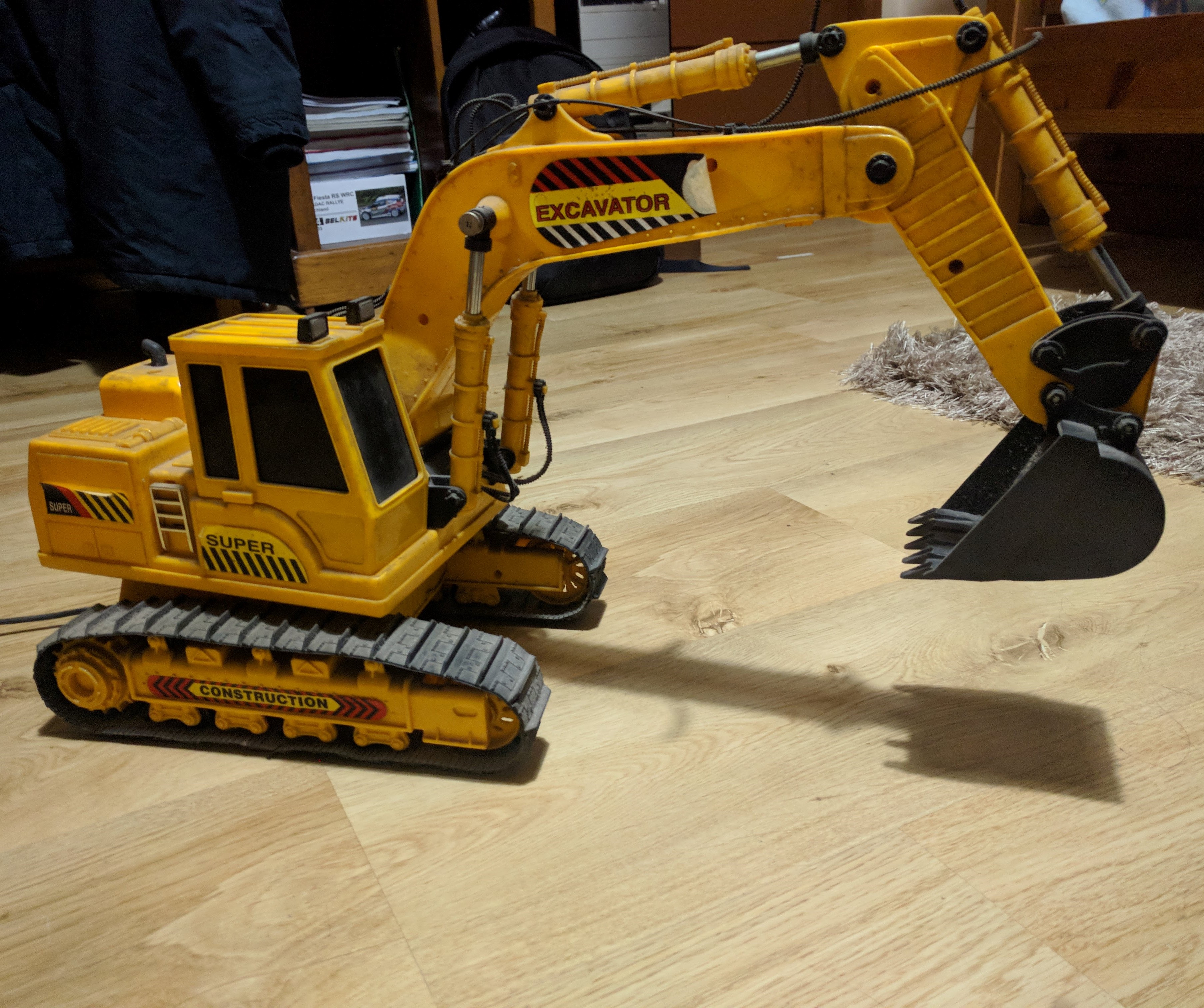
The object was disassembled piece by piece. Each of the pieces were registered and documented, then they were designed in Solidworks. The objective is to build small subassemblies, using a bottom-up approach.
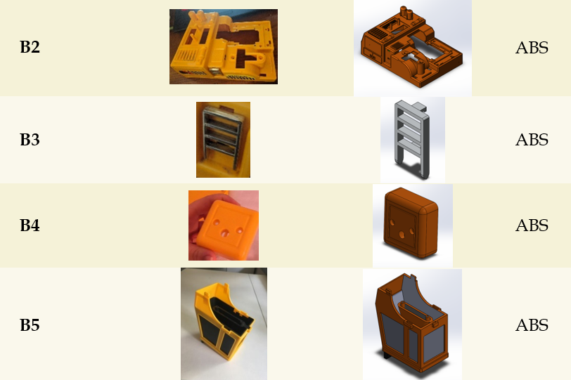
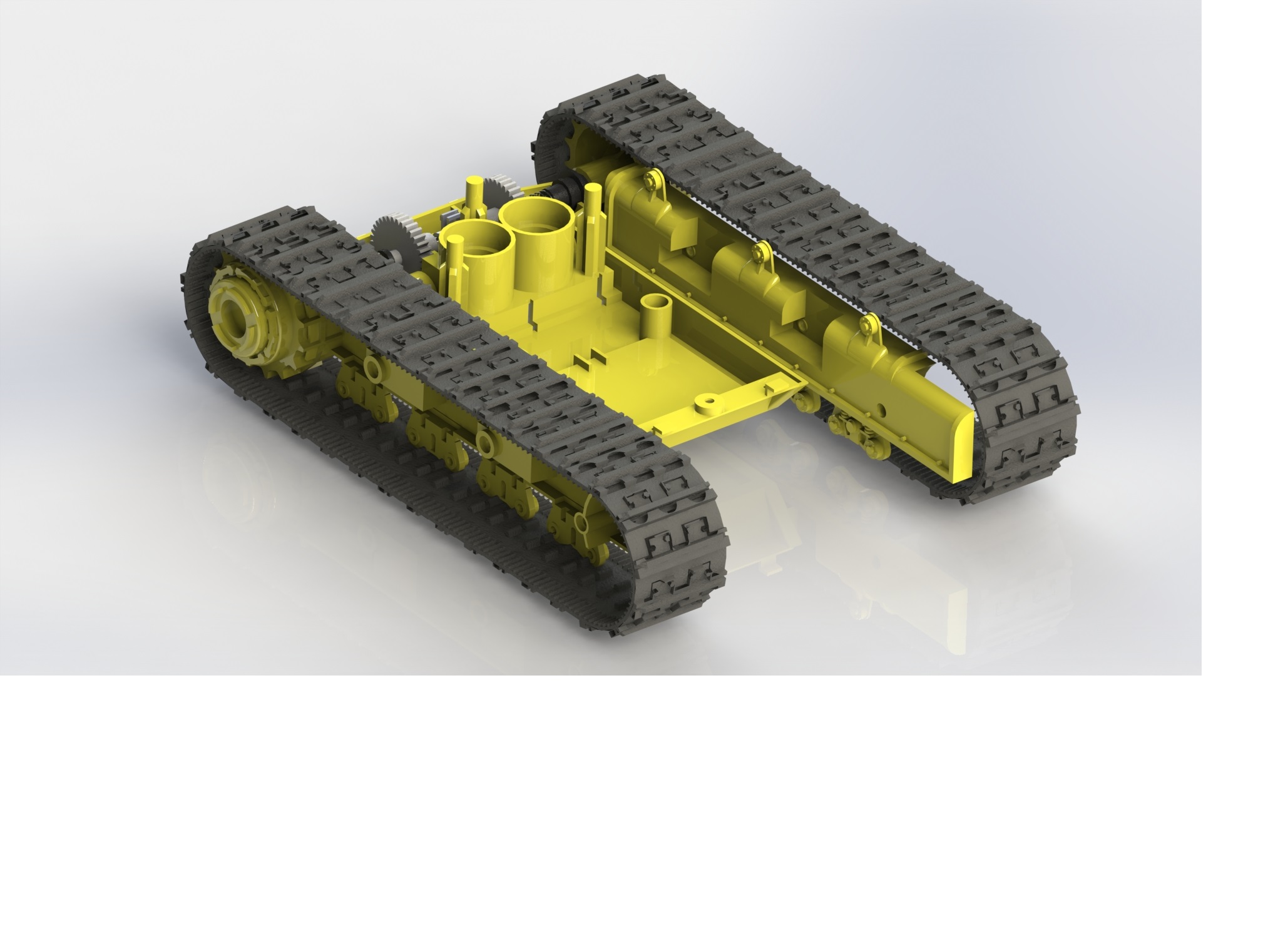
Diving the object by subassemblies demonstrated to be a valid approach for the project. The left picture is an example of one of the many subassemblies of the excavator.
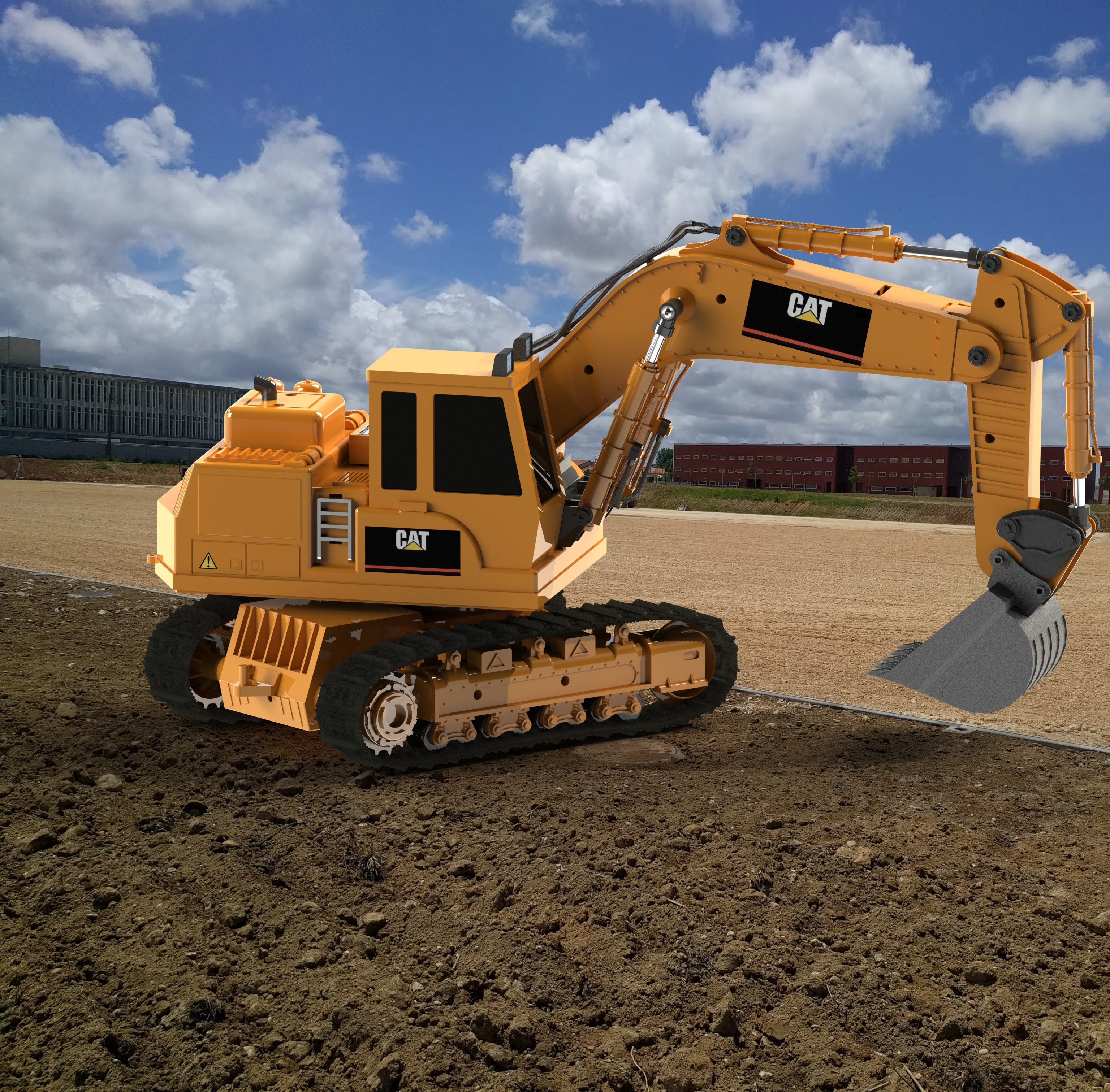
Throughout the project, I had been assembling the excavator focusing mainly on four assembly groups: 1st - the rotating base with the tracks; 2nd - the upper part with the engine and the cabin; 3rd - the arm with the gear mechanisms. Finally, to finish the CAD model, decals and textures (tracks and lights) were added to the excavator and photorealistic rendering was performed.
Fully assembled object
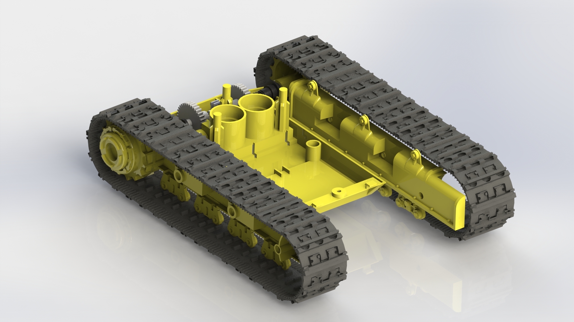
Bottom part containing the tracks and the gear mechanism which will rotate the track wheels.
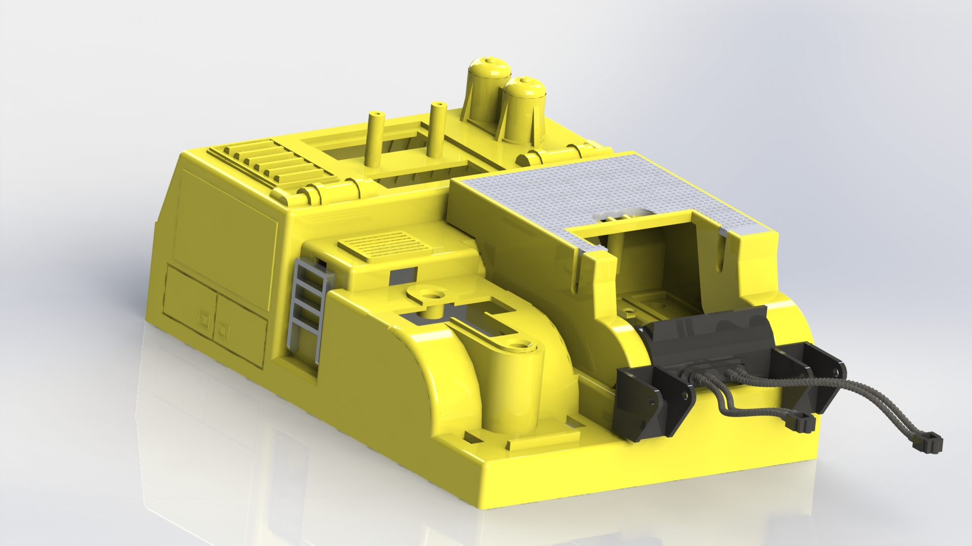
Contains the engine, the exhaust and the fixations for the operator cabin and excavator arm.
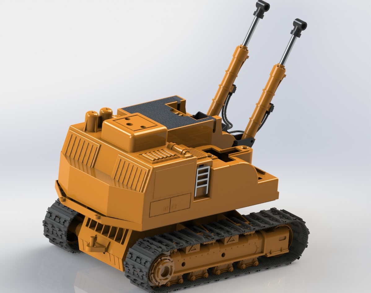
Bottom and upper part assembly, added hydraulic cylinders and adjusted color tone.
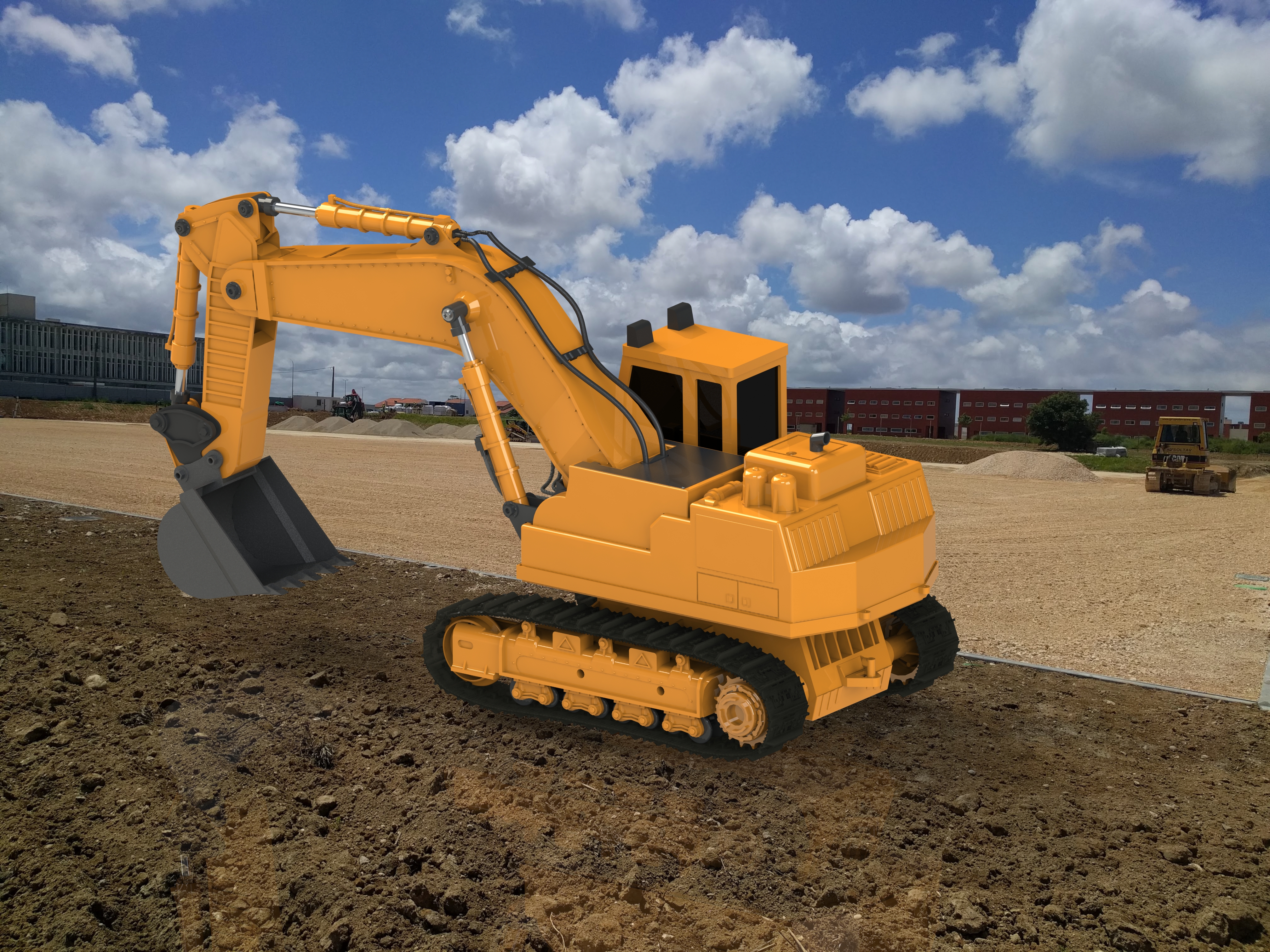
Added the fully assembled excavator arm to the core body assembly.
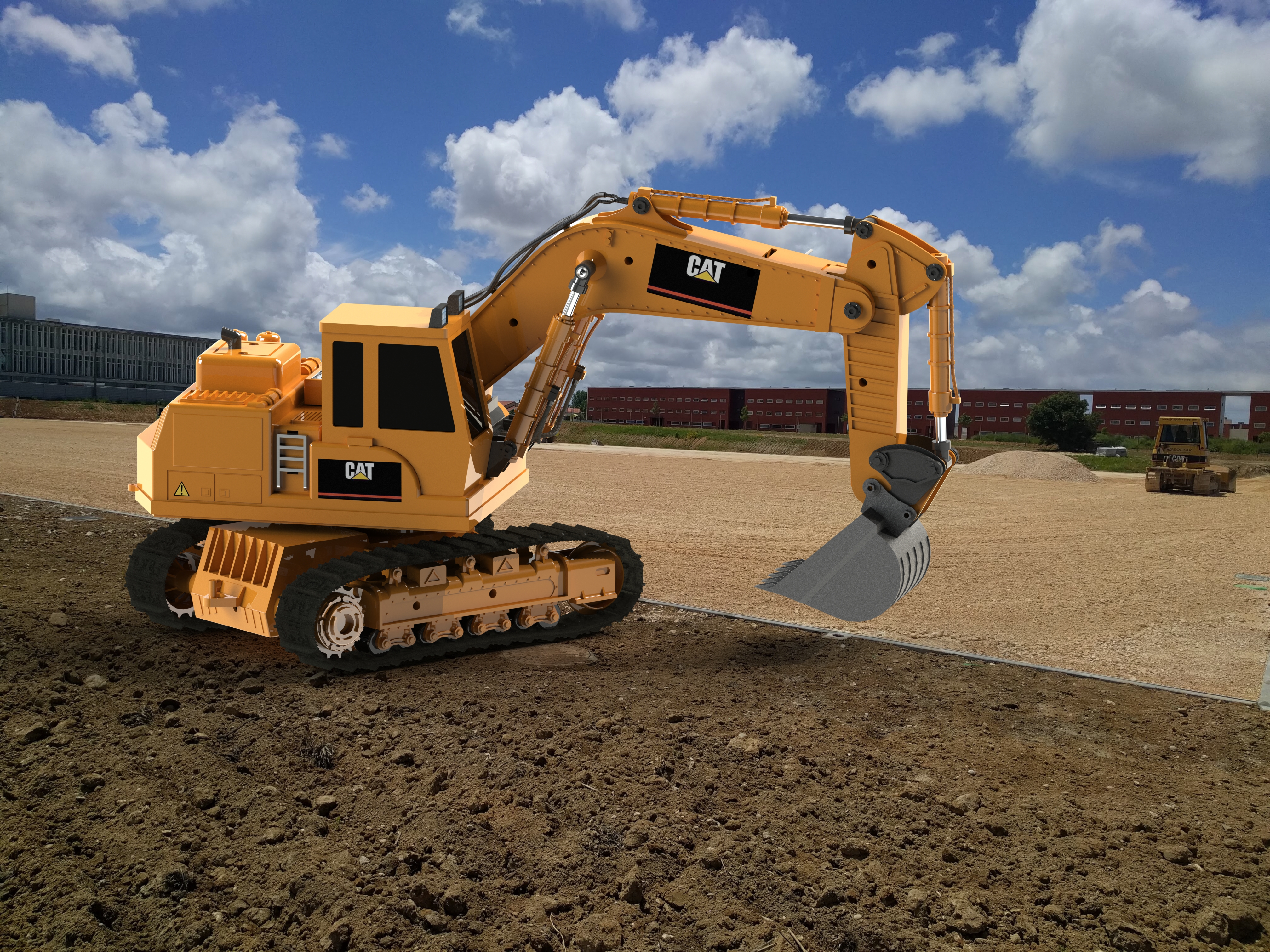
Added stickers and texture to the lights on top of the cabine. Added dynamic movement to all pieces connected by gear and hydraulic systems.
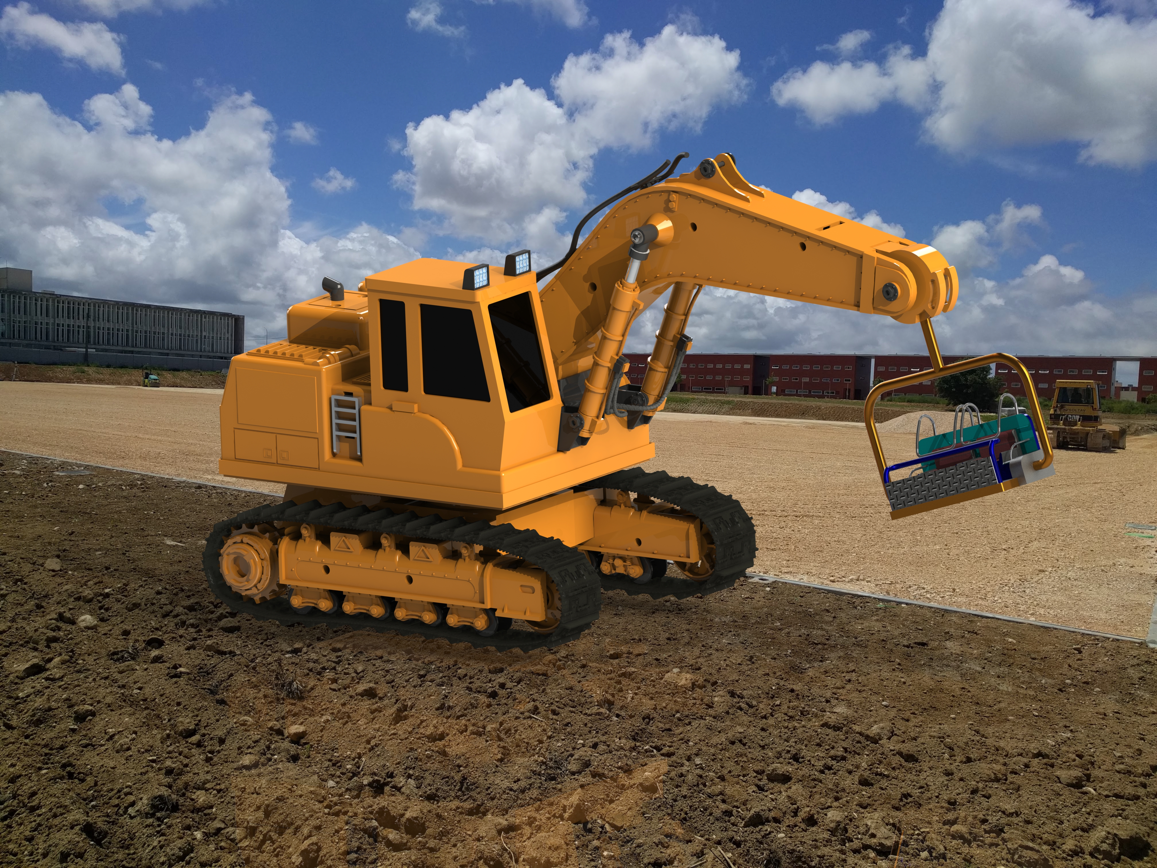
Redesigned the object function for a theme park joyride.
Project was a success and it proved to be a great tool to learn and practice 3D CAD using Solidworks. Modelling practices involved 3D solid design, surface design, assembly design, adding simple and complex assembly constraints, dynamics animation and photorealism rendering.
3D CAD; CAE
Drawings for Manufacturing
Group Project