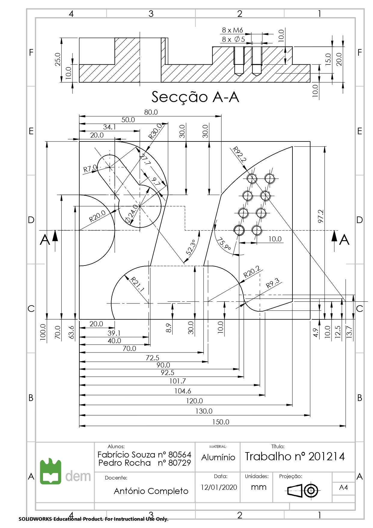
Part Drawing
Technical Drawing of the part to be produced in the university's CNC Machining Station.
This subject addresses CNC technology and focuses on understanding the science behind numerical control and also how to use it to manufacture a specific part.
Group Project: 2 people
The main objective of the subject is transmit knowledge regarding CNC technology, such as:
A part drawing was assigned to be manufactured using a CNC machining station. To produce the part, parameters for velocities of the tools rotation and depth of cut had to be calculated for a smooth and controlled machining operation. Machining operations used consisted of:
This project was divided in three parts. The first one was focused on drawing the electrical diagrams for assigned devices of the PLC and/or CNC machine. The second part focused on developing a PLC logical code to perform a set of actions given by the professor, such as a sequence of LED lights turning on and off and activating electrical outputs. The third part would be writing a short PLC and G-Code to activate the necessary outputs in order to have a CNC machine drawing the initial letters of the group members (2 people = 2 letters).
This project gallery contains some pictures, diagrams, schematics and some videos of actions being performed on both projects: CNC Machining Station and PLC-CNC Programming.
Technical Drawing of the part to be produced in the university's CNC Machining Station.
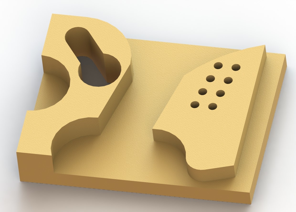
Having a 3D CAD model of the object is very useful to conveniently visualize the part in multiple angles and help defining the steps and procedures to manufacture it.
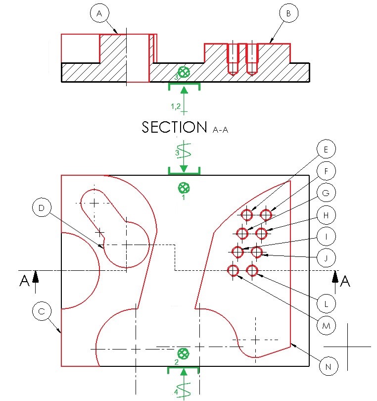
Each letter is tied to a reference that will have a certain amount of machining processes related to it.
Milling a certain volume of material that needs to be removed.
A total of 15 mm of depth to be removed where 3 mm of material is removed every cycle, up to a total of 5 cycles.
A total of 10 mm of depth to be removed where 3 mm of material is removed every cycle, up to a total of 4 cycles.
There is some material that neees to be removed after the last two cycles. Same operation for the material on the top.
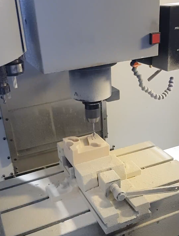
To produce the next feature on the part (a slot), we need to drill a hole so that the mill can be inserted.
The mill "draws" the slot profile my milling the sides. A change of axis system was made to ease this cycle.
The part contains two diagonal rows of M6 holes.
The M6 holes contain threads, hence a tapping procedure is needed.
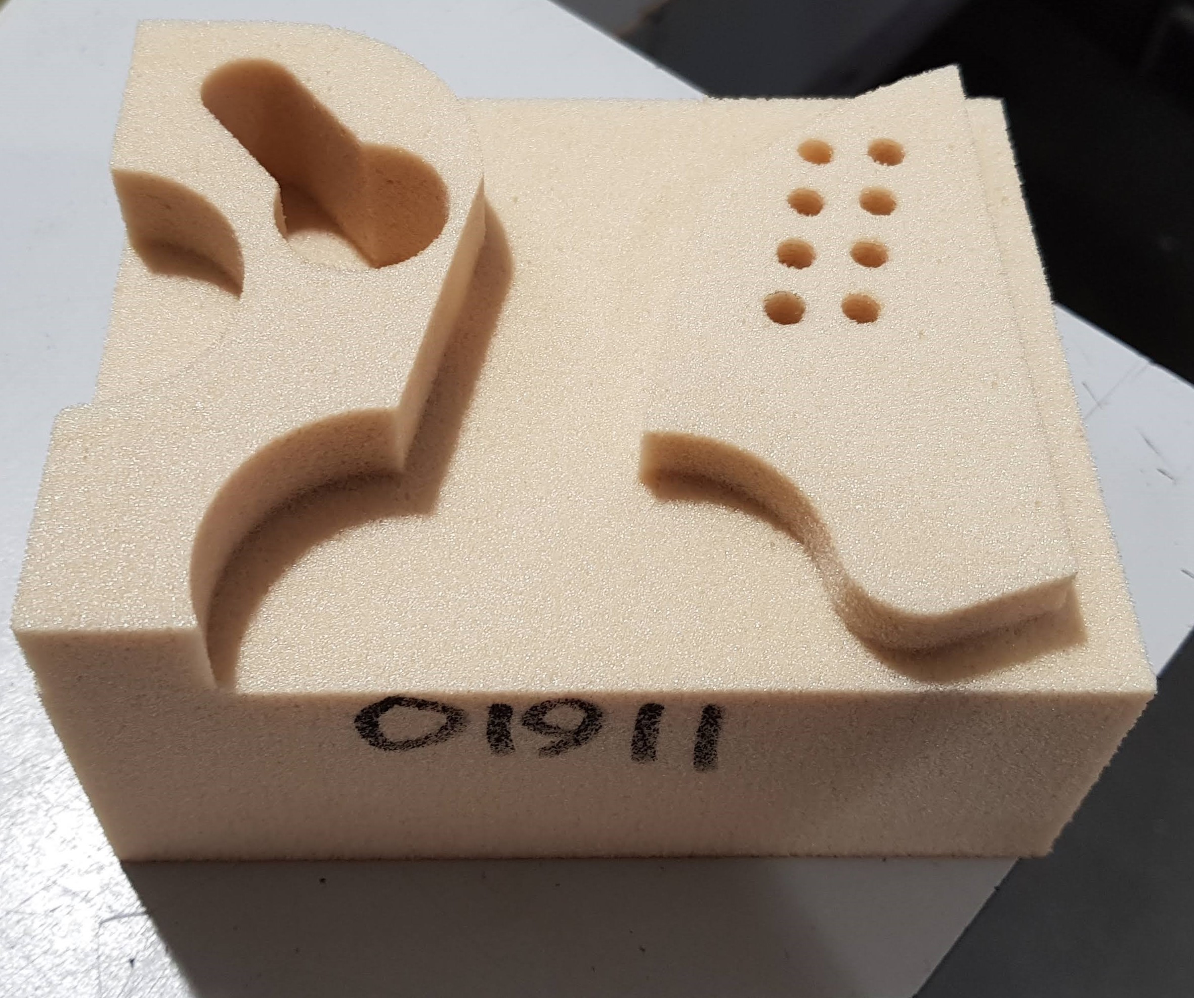
A photograh of the manufactured part.
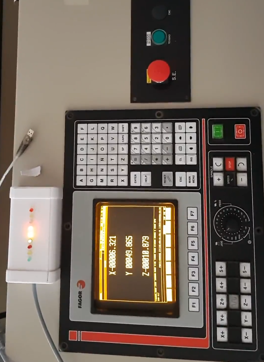
Through PLC programming, using a CNC we were able to control digital and physical output signals, using digital and physical inputs.
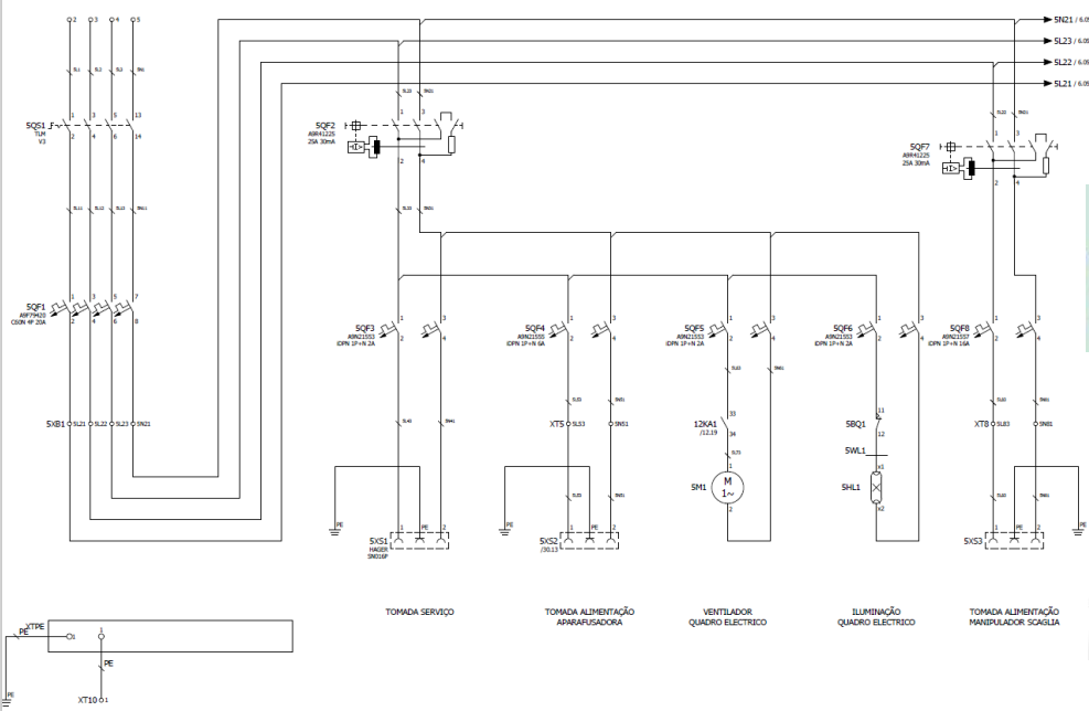
An example of an electric diagram for powering devices in the CNC-PLC controlled machine.
This subject presented the oportunity to closely study CNC technology. It was a thorough learning experience that featured applications in the manufacturing area but also the programming area. It was given the chance to program electrical equiment controlled by a PLC and also program a Mikron VCE 500 (HAAS VF-0) CNC Machining Station to produce a part.
Control and command CNC machining station to produce aluminium part.
Using Numerical Command to control PLC actions.